A stirring and centrifugal separation device for removing ferromagnetism architectural paint

A technology for architectural coatings and centrifugal separation, applied in magnetic separation, mixers with rotating stirring devices, centrifuges, etc., can solve the problems of architectural coatings sticking to the wall, increasing equipment installation costs, inability to separate ferromagnetic impurities, etc. The effect of convenient addition and discharge, improved stirring adequacy, and improved stability

Inactive Publication Date: 2019-04-30
湖北屹峡峰建设工程有限公司
View PDF7 Cites 0 Cited by
  • Summary
  • Abstract
  • Description
  • Claims
  • Application Information

AI Technical Summary

Problems solved by technology

Today's architectural coatings manufacturers generally use commonly used dispersers and mixing tanks to complete the process. After adding the emulsion resin to the mixing tank, add appropriate pigments, fillers and auxiliary materials to it, and realize the mixing of various raw materials through the stirring of the mixing tank. Preliminary mixing, the paint after preliminary mixing is dispersed at a high speed through a disperser, and for the production of architectural coatings, the materials that are mixed in the mixing tank are generally powdery or granular materials, which are usually stirred by the mixing tank. output, but the existing agitator is composed of a simple stirring rod, which is likely to cause the construction paint to stick to the wall. Insufficient mixing of architectural coatings; and only the rotation of the agitator can be realized, but the rotation of the inner cylinder cannot be realized. The driving mode is usually driven independently by different driving mechanisms, which increases the installation cost of the equipment, is not conducive to the stirring and separation of architectural coatings, and is harmful to The ferromagnetic impurities contained in it cannot be separated

Method used


Image

  • A stirring and centrifugal separation device for removing ferromagnetism architectural paint
  • A stirring and centrifugal separation device for removing ferromagnetism architectural paint
  • A stirring and centrifugal separation device for removing ferromagnetism architectural paint

Examples


Embodiment Construction

[0021] The following will clearly and completely describe the technical solutions in the embodiments of the present invention with reference to the accompanying drawings in the embodiments of the present invention. Obviously, the described embodiments are only some, not all, embodiments of the present invention. Based on the embodiments of the present invention, all other embodiments obtained by persons of ordinary skill in the art without making creative efforts belong to the protection scope of the present invention.

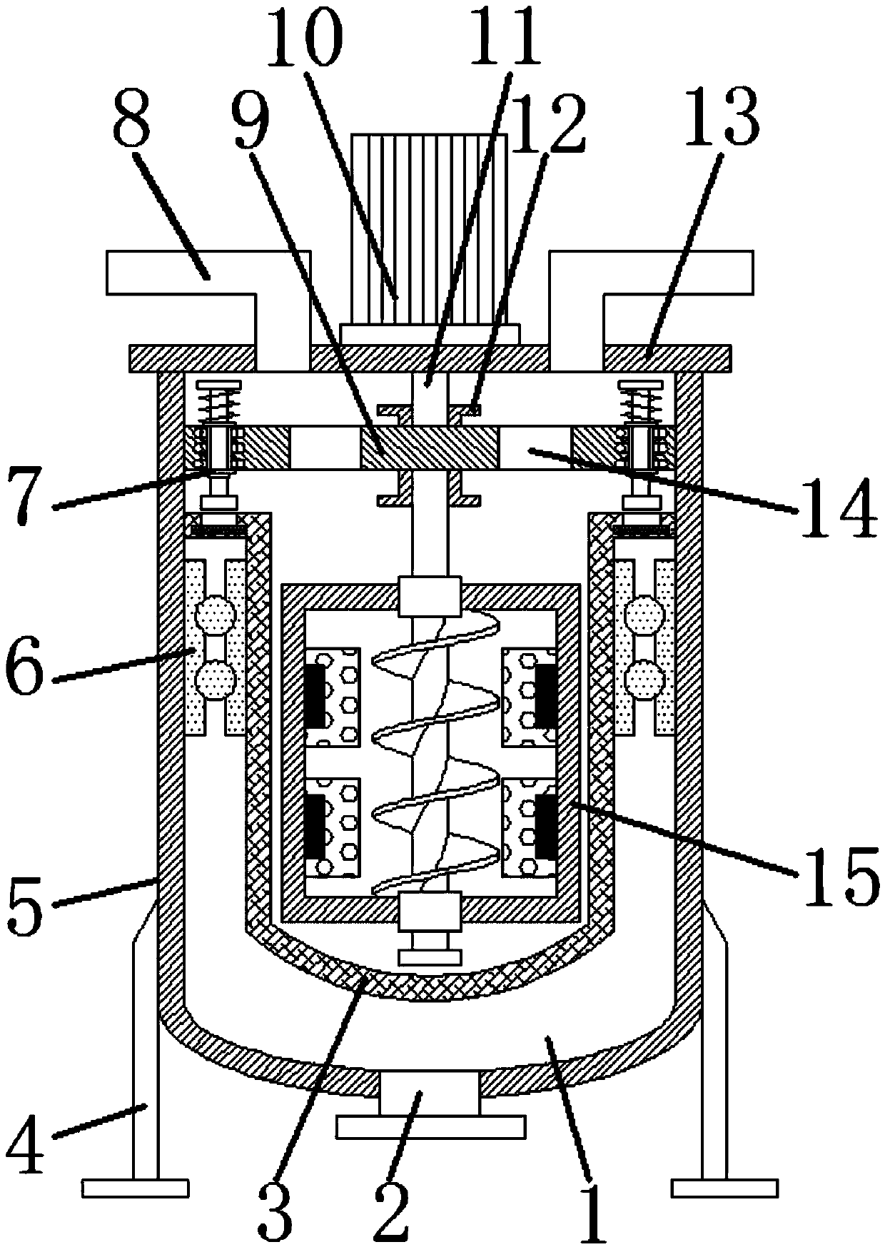
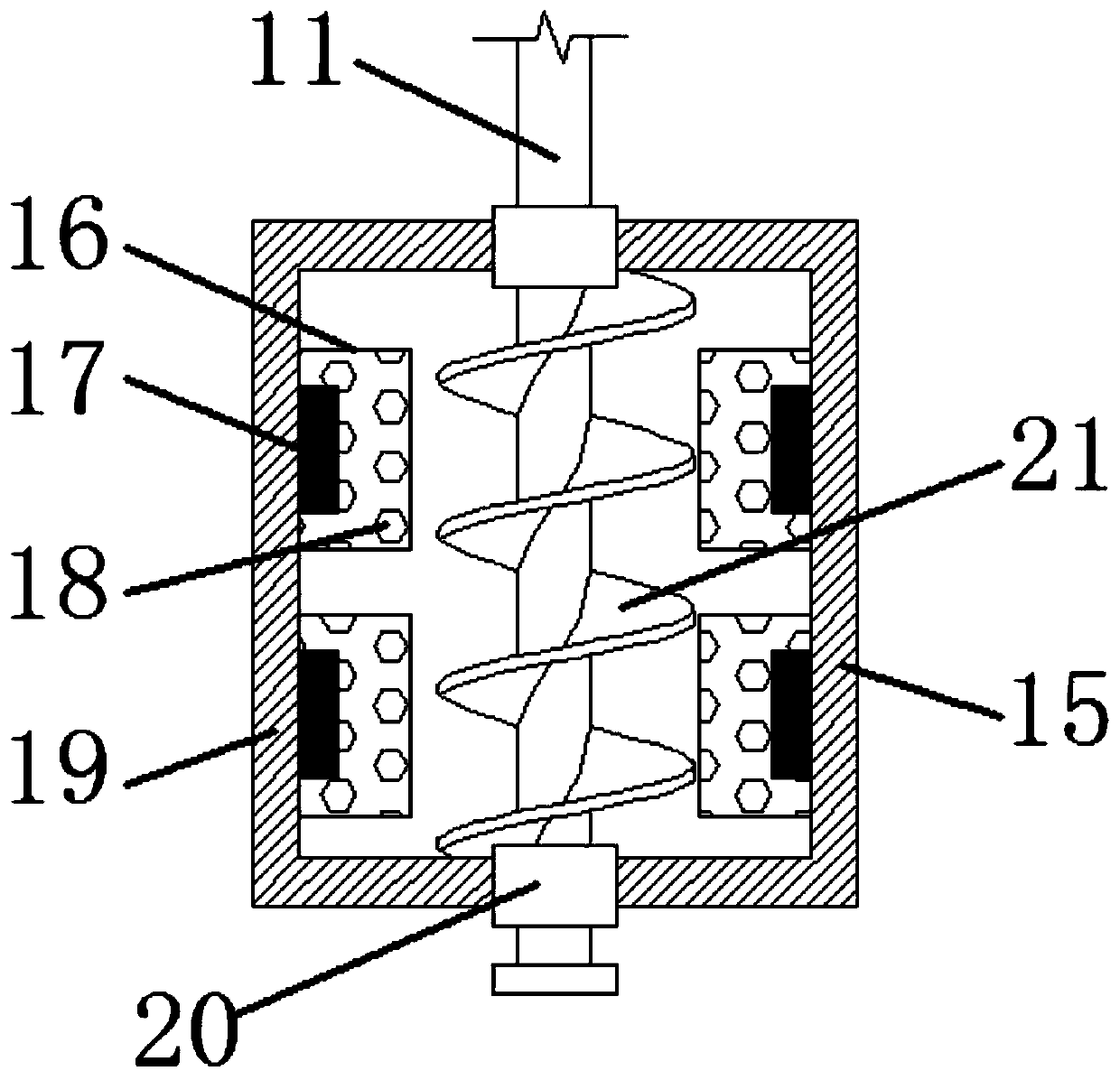
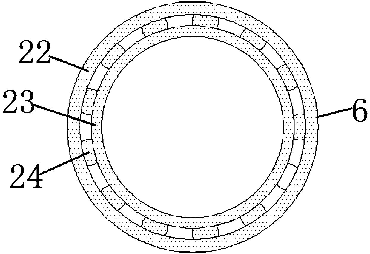
[0022] see Figure 1~4 , in an embodiment of the present invention, a stirring and centrifuging device for removing ferromagnetism building paint, comprising a centrifugal separation cylinder 3, a building paint tank 5, a ball bearing 6, an electromagnetic drive mechanism 7, a rotating disk 9 and a rotating shaft 11, The bottom of the architectural paint tank body 5 is installed on the frame 4, the interior of the architectural paint tank body 5 is set as the ...


PUM


Abstract

The invention discloses a stirring and centrifuging device for removing ferromagnetism building paint, which comprises a centrifugal separation cylinder, a building paint tank, a ball bearing, an electromagnetic drive mechanism, a rotating disk and a rotating shaft. The bottom of the building paint tank is installed on On the frame, a ball bearing is installed on the inner wall of the building paint tank, a centrifugal separation cylinder is placed inside the ball bearing, an agitator is installed inside the centrifugal separation cylinder, and the agitator is installed at the bottom of the rotating shaft. A rotating disk is installed on the rotating shaft above the body, and a number of material guide holes are arranged on the rotating disk, and an electromagnetic drive mechanism is installed on the rotating disk; the stability of the rotation of the centrifugal separation cylinder is improved, and the protection against architectural coatings is improved. Stirring is sufficient to effectively absorb ferromagnetic impurities in architectural coatings. Under the rotation of the rotating disc, the iron core rod drives the centrifugal separation cylinder to rotate, which is convenient to realize the centrifugal treatment of architectural coatings by the rotation of the centrifugal separation cylinder.

Description

technical field [0001] The invention relates to the technical field of construction equipment, in particular to a stirring and centrifugal separation device for removing ferromagnetism architectural coatings. Background technique [0002] In the past few years or even in the next few years, construction has been the main industry that stimulates domestic demand and consumption, and the development of the construction industry is inseparable from various architectural coatings. Unlike other industries that use coatings, the production of coatings in the construction industry The process is generally to directly purchase the raw material emulsion, and then add the required pigments, fillers and various auxiliary materials to the raw material emulsion. The chemical changes involved are relatively small, and the main process is stirring and dispersing. Today's architectural coatings manufacturers generally use commonly used dispersers and mixing tanks to complete the process. Af...

Claims


Application Information

Patent Timeline
Patent Type & Authority Patents(China)
IPC IPC(8): B04B5/10B03C1/12B01F7/00B01F7/24
CPCB03C1/12B04B5/10B01F27/00B01F27/074B01F27/92B01F2101/30
Inventor 黎英姿
Owner 湖北屹峡峰建设工程有限公司
Why Eureka
Try Eureka