Structural design of a two-dimensional multi-plate ejector

A two-dimensional configuration and ejector technology, which is applied in the directions of jet pumps, mechanical equipment, machines/engines, etc., can solve the problems of large flow loss of the ejected airflow, complex nozzle arrangement, and affecting ejection performance. Achieve the effect of improving ejection performance, compact structure and reducing shock loss

Active Publication Date: 2019-09-27
NAT UNIV OF DEFENSE TECH
View PDF5 Cites 0 Cited by
  • Summary
  • Abstract
  • Description
  • Claims
  • Application Information

AI Technical Summary

Problems solved by technology

[0003] At present, the technology of multi-nozzle ejectors at home and abroad is mostly based on the axisymmetric configuration, that is, the supersonic nozzle and gas flow channels are all axisymmetric configurations, and the technology of multi-nozzle ejectors is mostly circular Multiple groups of axisymmetric nozzles are built into the channel, and the axisymmetric nozzles are generally designed in an "L" shape. In order to reduce the vibration of the pipeline, supports will be provided between the nozzles. Disadvantages of large flow loss of airflow
In addition, the uneven distribution of the ejected airflow and the ejected airflow in the mixing chamber in the multi-nozzle ejector with axisymmetric configuration will cause a large shock wave loss, which will affect the ejection performance

Method used


Image

  • Structural design of a two-dimensional multi-plate ejector
  • Structural design of a two-dimensional multi-plate ejector
  • Structural design of a two-dimensional multi-plate ejector

Examples


Embodiment 1

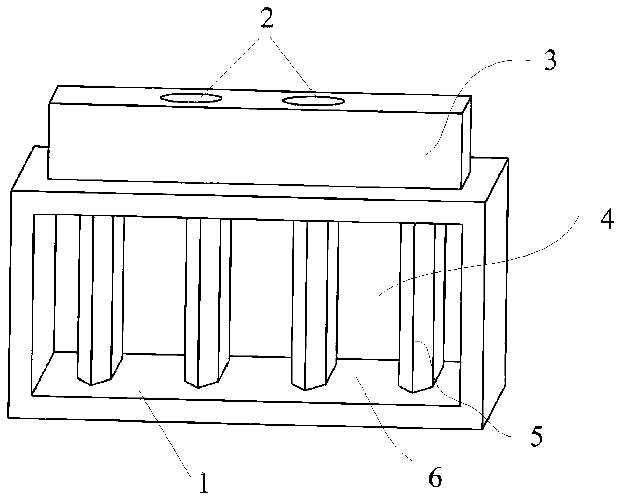
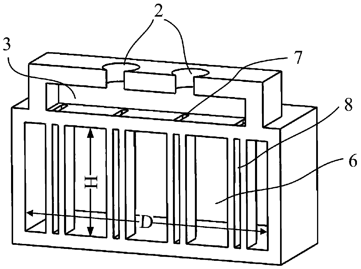
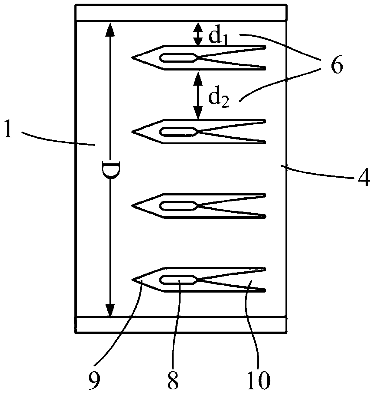
[0029] As shown in the accompanying drawings, the present invention proposes a two-dimensional multi-branch ejector structure design, which is characterized in that the interior of the ejector is provided with multiple sets of splitters for the ejected airflow and the ejected airflow Support plate, one end of the ejector is provided with an ejected air inlet for introducing the ejected airflow, the side wall of the ejector is provided with an air collection chamber, and the air collection chamber is provided with an ejected airflow for introducing the ejected airflow Inlet, the inside of the support plate is provided with a nozzle air guide chamber, the nozzle air guide chamber and the gas collection chamber are connected through the air inlet of the nozzle air guide chamber, and the inside of the support plate is provided with a two-dimensional Laval nozzle, a two-dimensional Laval nozzle The inlet of the nozzle is connected to the air guide cavity of the nozzle, and the outle...

Embodiment 2

[0041] As shown in the accompanying drawings, the present invention proposes a two-dimensional configuration of multi-branch ejector structure design, and the design steps of the ejector are as follows:

[0042] S1, determining airflow parameters;

[0043]According to the physical parameters and performance requirements of the ejected airflow and the ejected airflow, the physical parameters include specific heat ratio and viscosity, etc., and the performance requirements include the ejection coefficient and pressurization ratio, and the ejector airflow is determined through the one-dimensional design theory of the ejector The parameters of the ejected airflow, where the Ma number of the ejected airflow is 4, the total pressure is 3MPa, the Ma number of the ejected airflow is 0.4, and the total pressure is 12kPa;

[0044] S2, setting the inner channel size of the ejector;

[0045] Set the width of the inner cavity of the ejector to be D=850mm, the height to be H=350mm, the inn...


PUM


Abstract

The invention provides two-dimensional construction multi-support-plate ejector structural design and belongs to the technical field of ejector structural design. Multiple sets of support plates for dividing ejecting airflow and ejected airflow are arranged in an ejector. Flow guide sections are arranged at the front ends of the support plates, and spraying tube air guide cavities and two-dimensional laval jet tubes are arranged in the support plates. The ejecting airflow is divided into multiple streams of uniform airflow by the two-dimensional laval jet tubes in the support plates. The ejected airflow is divided into multiple streams of uniform airflow by ejected airflow subchannels between the support plates, then the contact area between the ejecting airflow and the ejected airflow isincreased, and a better mixing effect is achieved. Through the two-dimensional construction multi-support-plate ejector structural design, shock wave loss is lowered effectively while mixing adequacyof the ejecting airflow and the ejected airflow is enhanced, and then ejecting performance of the ejector is improved.

Description

technical field [0001] The invention belongs to the technical field of ejector application, and in particular relates to a structural design of a two-dimensional configuration multi-branch ejector. Background technique [0002] An ejector is a gas machine that pressurizes a low total pressure airflow by means of a high total pressure airflow. Mechanistically, the ejector transmits the kinetic energy of the ejected airflow to the ejected airflow through the transport of turbulent flow in the mixed layer in contact between the ejected airflow and the ejected airflow to increase the total pressure of the ejected airflow. Effect. Therefore, enhancing the mixing between the ejected airflow and the ejected airflow is a main way to improve the performance of the ejector. There are two ways to enhance the mixing: increasing the mixing area between the ejected airflow and the ejected airflow, and designing the outlet of the special-shaped nozzle to enhance the disturbance between t...

Claims


Application Information

Patent Timeline
Patent Type & Authority Patents(China)
IPC IPC(8): F04F5/16F04F5/44
Inventor 徐万武叶伟李平张富强
Owner NAT UNIV OF DEFENSE TECH
Why Eureka
Try Eureka