Air foam flooding shaft bottom foaming process pipe column

A technology of air foam flooding and process strings, which is applied in the direction of wellbore/well components, wellbore/well valve devices, production fluids, etc., and can solve the fatal damage of compressors, foam inhomogeneity, and liquid backflow into compression Machine and other problems, to reduce the risk of pipe string corrosion, good leak-proof effect, save expensive investment effect

Active Publication Date: 2012-01-04
PETROCHINA CO LTD
View PDF7 Cites 11 Cited by
  • Summary
  • Abstract
  • Description
  • Claims
  • Application Information

AI Technical Summary

Problems solved by technology

[0003] At present, there are two types of process strings used in oilfields for foam injection: (1) The structure of the permanent packer gas-filled sealing tubing, the injection method mostly adopts the alternate injection of gas and liquid to mix and form foam in the formation. The disadvantages of the injection method are: ① When the gas-liquid exchange needs to reverse the wellhead valve, it is easy to cause the liquid injected into the wellbore to flow back into the compressor, causing fatal damage to the compressor; it may also cause the gas to flow back into the injection pump to reduce pump efficiency; ② Due to the heterogeneity in the formation, it is easy to cause the inhomogeneity of the foam formation, and the experiment shows that the mixed injection of air and foam agent has a stro

Method used


Image

  • Air foam flooding shaft bottom foaming process pipe column
  • Air foam flooding shaft bottom foaming process pipe column
  • Air foam flooding shaft bottom foaming process pipe column

Examples


Embodiment Construction

[0023] In order to have a clearer understanding of the technical features, purposes and effects of the present invention, the specific implementation manners of the present invention will now be described with reference to the accompanying drawings.

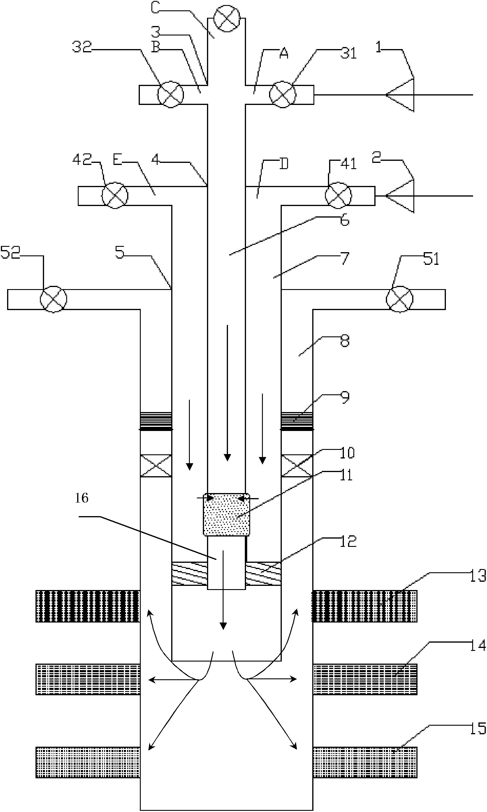
[0024] Such as figure 1 As shown, the present invention proposes an air foam flooding bottomhole foaming process string, and the air foam flooding bottomhole foaming process string at least includes: an inner pipe 6 and an outer pipe sleeved outside the inner pipe 6 7. The two form a concentric column. In this way, the process string of the present invention has two passages, respectively through the inner pipe and the annular space formed between the inner pipe and the outer pipe, the gas and the liquid are separated from each other, and the air and the liquid each go through an independent passage, so Reduced risk of string corrosion.

[0025] Further, an annular space is formed between the inner tube 6 and the outer tube 7, ...


PUM


Abstract

The invention discloses an air foam flooding shaft bottom foaming process pipe column, which at least comprises an inner pipe and an outer pipe arranged outside the inner pipe. The air foam flooding shaft bottom foaming process pipe column also adopts a ground-matched check valve to simplify ground valve switching operation and reduce the risk of damaging a topping-up pump and an air compressor; because double-pipe injection is adopted, the air and liquid pass through an independent passage respectively to reduce the risk of pipe column corrosion; and a foam generator is arranged at the bottom of a well to generate foams near the well bottom so that the performance of injected foams is guaranteed and the foams better play a role in the displacement of reservoir oil and profile control.

Description

technical field [0001] The invention relates to the field of oil production machinery, and relates to an air foam driving well bottom foaming process string. Background technique [0002] Air foam flooding is to use injection wells to inject air foam into oil layers. It not only has the dual functions of profile control and oil displacement, but also uses the flue gas drive effect of oxidation products and the heat generation effect of oxidation to recover oil. [0003] At present, there are two types of process strings used in oilfields for foam injection: (1) The structure of the permanent packer gas-filled sealing tubing, the injection method mostly adopts the alternate injection of gas and liquid to mix and form foam in the formation. The disadvantages of the injection method are: ① When the gas-liquid exchange needs to reverse the wellhead valve, it is easy to cause the liquid injected into the wellbore to flow back into the compressor, causing fatal damage to the compr...

Claims


Application Information

Patent Timeline
IPC IPC(8): E21B43/22E21B33/10E21B34/02
Inventor 王伯军马德胜蒋有伟王红庄李秀峦张志远陈亚平梁金中关文龙韩静李晓玲刘双卯罗建华王冰王春雨卞小强于斌
Owner PETROCHINA CO LTD
Why Eureka
Try Eureka