
Thermocline solar thermal storage system with baffles

A technology of heat storage system and baffle plate, which is applied in the field of solar heat storage system, can solve the problems of system operation efficiency decrease, complex structure, high cost, etc., achieve heat storage efficiency and operation performance improvement, wide applicable temperature range, processing and installation low cost effect

Inactive Publication Date: 2012-01-04
INST OF ELECTRICAL ENG CHINESE ACAD OF SCI
View PDF4 Cites 7 Cited by
  • Summary
  • Abstract
  • Description
  • Claims
  • Application Information

AI Technical Summary

Problems solved by technology

However, when the system is running, the thickness of the thermocline accounts for a large proportion of the height of the tank, and the expansion of the thermocline caused by heat conduction and local turbulence (that is, the mixing of high and low temperature fluids) is difficult to suppress, resulting in a gradual decline in the operating efficiency of the system , the system is unstable
[0005] In order to avoid the reduction of system efficiency caused by the mixing of cold and hot fluids during the operation of the thermocline heat storage system, active or passive horizontal partitions or vertical partitions are introduced into some patented designs, such as US patents US4523629, US4543978, US4643212 , US20100301062A1, Chinese patent CN201184766Y, etc.
When this type of system is running, the partition moves actively or passively with the entry and exit of cold and hot fluids, directly separating the cold and hot fluids, avoiding direct contact between the cold and hot fluids, and having high heat storage efficiency, but the structure is more complicated , the cost is high, and only liquid can be used as heat exchange and heat storage medium, solid heat storage medium cannot be introduced, and it is not suitable for heat storage systems that use gas as heat exchange fluid and solid as heat storage medium

Method used


Image

  • Thermocline solar thermal storage system with baffles
  • Thermocline solar thermal storage system with baffles
  • Thermocline solar thermal storage system with baffles

Examples


Embodiment Construction

[0027] The present invention will be further described below in conjunction with the accompanying drawings and specific embodiments.

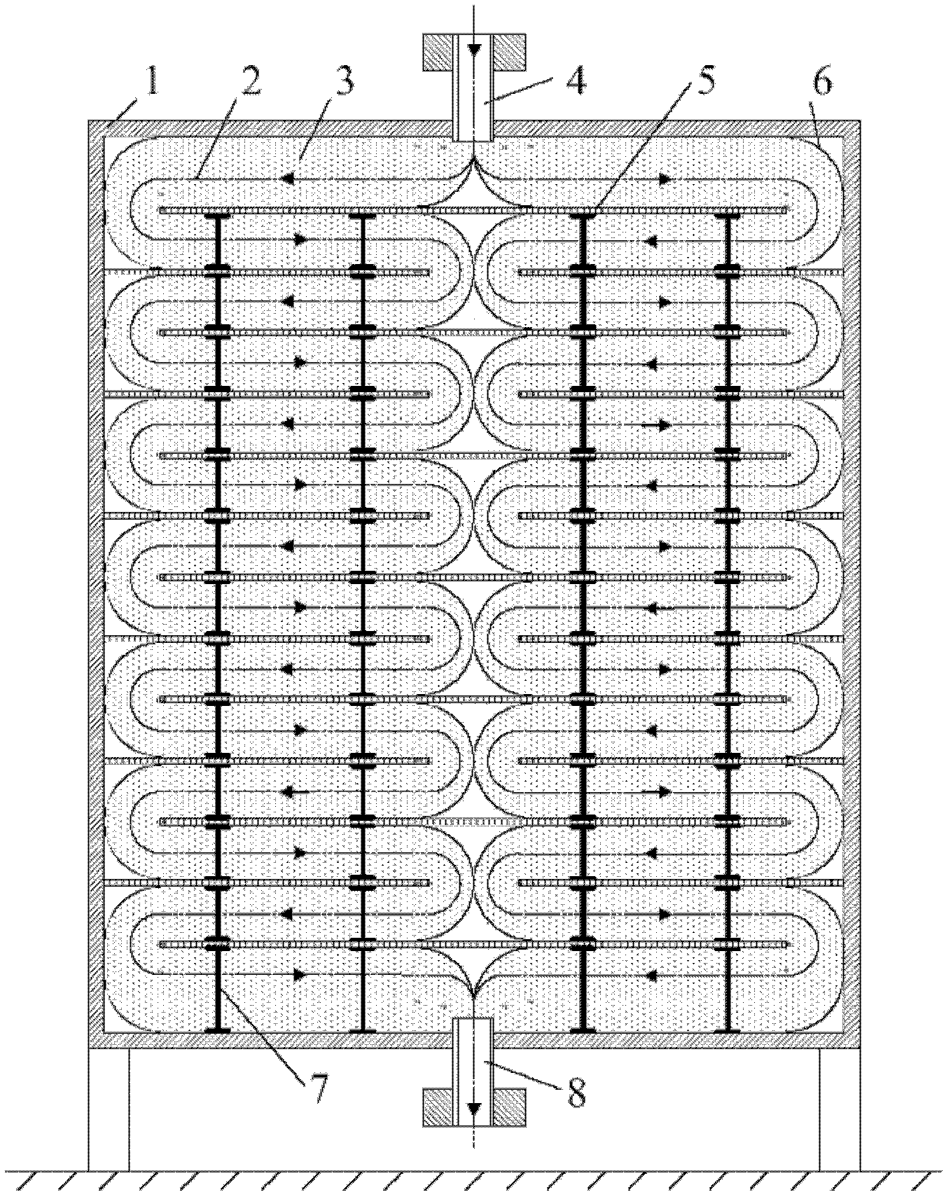
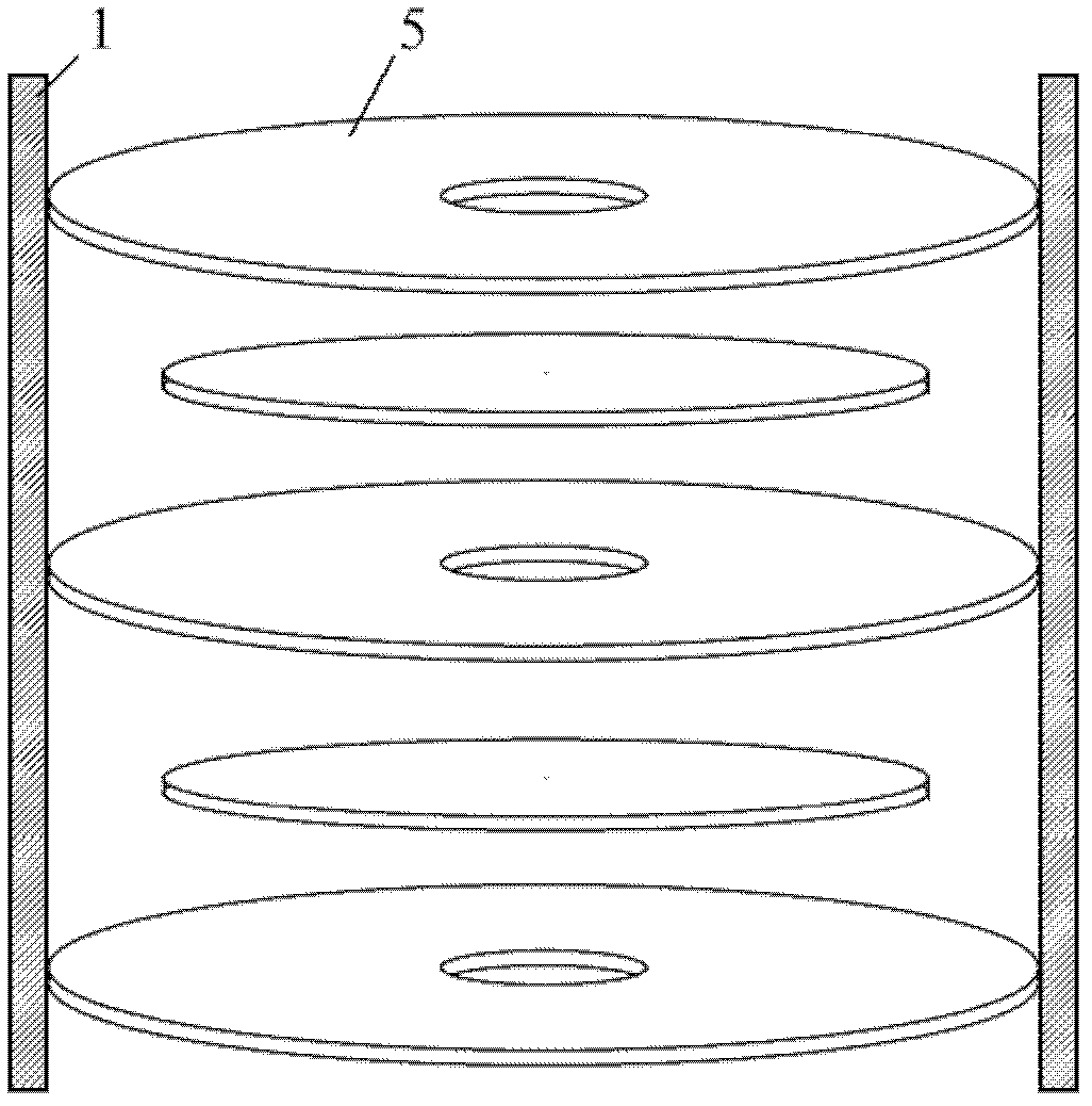
[0028] Such as figure 1 As shown, the heat storage system in Example 1 of the present invention is a cylindrical tower tank type thermocline heat storage system with multiple baffles arranged horizontally in the tank. The outer surface of the tank body 1 of the heat storage tank is wrapped with an insulating layer. The upper and lower ends of the heat storage tank are respectively equipped with an open pipe 4 and 8 for the heat exchange fluid to enter and exit the heat storage tank. Through the step-by-step support and installation of multiple structural pillars 7 in the heat storage tank, multiple parallel baffles 5 with low thermal conductivity are arranged horizontally. Under the action of the baffles, two parallel baffles are formed in the heat storage tank. Serpentine runner 2. The serpentine channel is filled with solid particles or po...


PUM


Abstract

The invention discloses a thermocline solar thermal storage system with baffles, comprising a thermal storage tank with a thermal insulation layer wrapped on the outer surface, wherein a plurality of parallel thin baffles with low conductivity are arranged in the thermal storage tank, and two ends of the thermal storage tank are respectively provided with an opening path. The baffles are arranged in multiple layers in the thermal storage tank in a staggering manner. One or more serpentine paths are formed in the thermal storage tank under the effect of the baffles. Cambered transition bending plates are arranged at the corners of the paths. The thermocline solar thermal storage system with baffles can be applied to middle / high-temperature solar thermal power generation, and other middle / high-temperature solar energy utilization fields.

Description

technical field [0001] The invention relates to a solar heat storage system, in particular to a thermocline solar heat storage system. Background technique [0002] In the field of solar thermal utilization, especially in the field of solar thermal power generation, due to the strong instability of solar radiation, the operation of the system also has strong fluctuations and intermittent. In order to overcome this difficulty, solar heat utilization systems generally have heat storage systems. The heat storage system can convert the solar radiation during the day into heat and store it, and then release the heat for use when there is no solar radiation. Especially for the field of solar thermal power generation, the introduction of the heat storage system can not only "shift the peak and fill the valley" of solar energy to prolong the power generation time of the system, but also effectively stabilize the system operation and improve the power generation efficiency of the sy...

Claims


Application Information

Patent Timeline
IPC IPC(8): F24J2/34F24J2/46
CPCY02E10/40F28D20/00F28D2020/0086Y02E60/14Y02E70/30
Inventor 徐超王志峰李鑫白凤武
Owner INST OF ELECTRICAL ENG CHINESE ACAD OF SCI
Learn More