Rock triaxial compression acoustic emission test system

A test system and triaxial compression technology, applied in the field of test systems, can solve problems such as inability to perform triaxial compression tests on rocks, and achieve reliable results for mine disasters

Inactive Publication Date: 2012-01-04
SHANDONG UNIV OF SCI & TECH
View PDF2 Cites 27 Cited by
  • Summary
  • Abstract
  • Description
  • Claims
  • Application Information

AI Technical Summary

Problems solved by technology

[0010] The purpose of the present invention is to solve the problem that the existing rock servo test system cannot perform triaxial com

Method used


Image

  • Rock triaxial compression acoustic emission test system
  • Rock triaxial compression acoustic emission test system
  • Rock triaxial compression acoustic emission test system

Examples


Embodiment Construction

[0024] Embodiments of the present invention will be further described below in conjunction with the accompanying drawings.

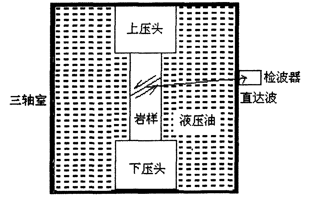
[0025] figure 1 It is a schematic diagram of the arrangement of the existing rock triaxial compression acoustic emission experiment. It can be seen from the figure that since the acoustic emission detector cannot be placed on the base, the acoustic emission detector can only be placed on the outer wall of the triaxial chamber.

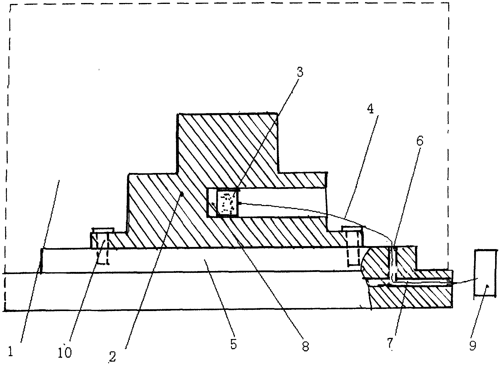
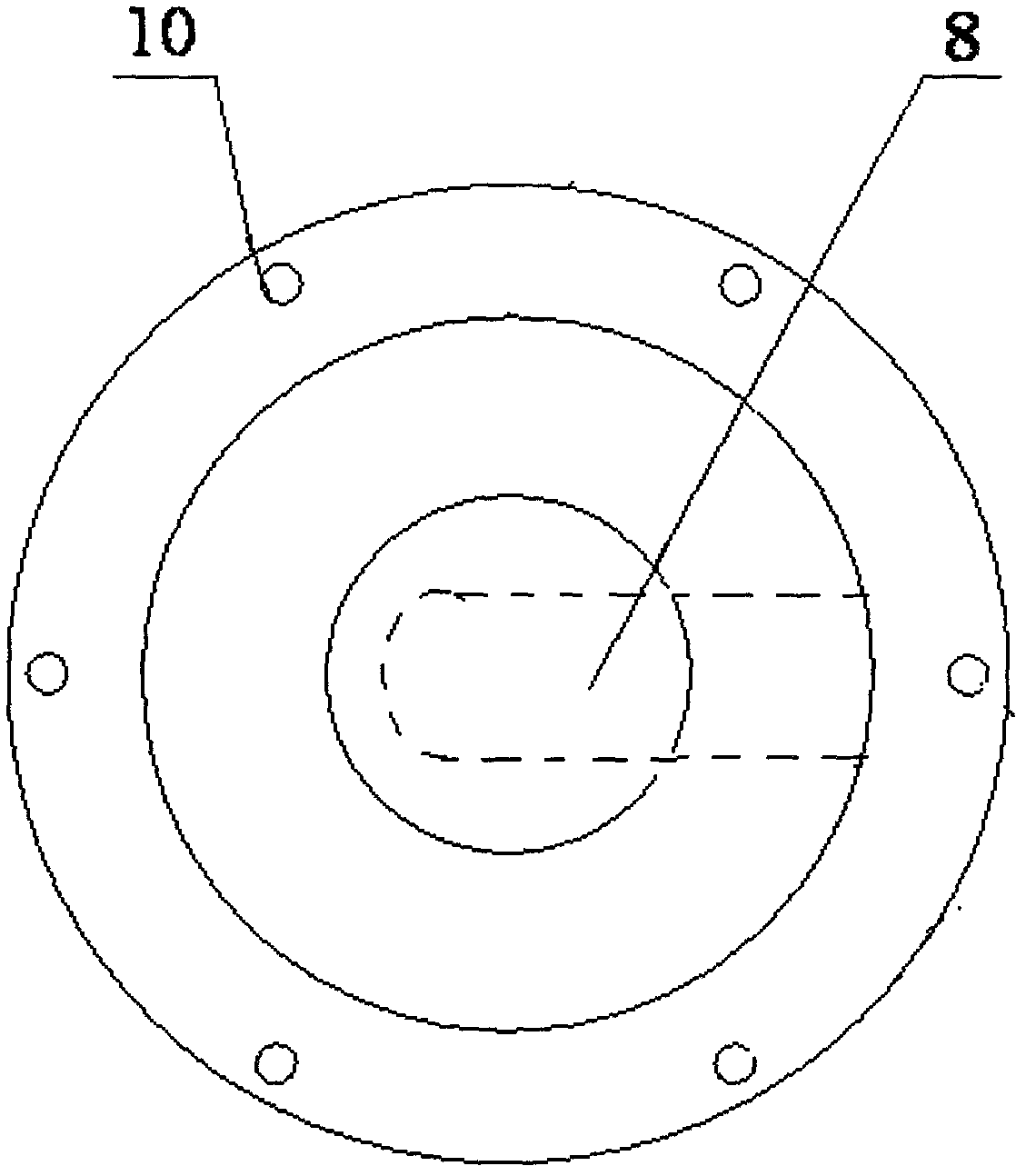
[0026] like figure 2 and image 3 As shown, the rock triaxial compression acoustic emission test system of the present invention is provided with an upper indenter (not shown in the figure) and a boss-shaped bottom indenter 2 in the triaxial chamber 1 of the existing MTS815 rock servo test system A cavity 8 opening to one side is processed on the thick diameter part of the bottom indenter 2. The cavity 8 is located on the indentation axis directly below the rock sample. The bottom of the bottom indenter 2 is also provided with...


PUM


Abstract

The invention discloses a rock triaxial compression acoustic emission test system, comprising a mechanics testing system (MTS) 815 rock servo test system, wherein a triaxial chamber of the system is internally provided with an upper pressure head and a bottom pressure head; an acoustic emission detector is arranged in the bottom pressure head; a shield signal of the acoustic emission detector penetrates out the triaxial chamber from a reserved communication channel of a base of the system; and a shield signal line is connected with a preamplifier, so as to realize outdoor transmission of a detection signal of the acoustic emission detector. By utilizing the rock triaxial compression acoustic emission test system disclosed by the invention, the acoustic emission signal can be monitored more comprehensively and truly; and the test system can be used for providing a more reliable test method and test results for predicating rock fracture, so as to prevent mine disaster accidents generated in rock body fracture.

Description

technical field [0001] The invention relates to a test system, in particular to a test system for rock triaxial compression acoustic emission. Background technique [0002] Underground mine roof fall, roof and floor water inrush, rock burst and other disasters and accidents occur from time to time, causing great harm to the life and property of the country and people. The occurrence of these disasters and accidents is closely related to rock mass rupture and instability. When the rock material bears the load, there will be a local elastic-plastic energy concentration phenomenon inside it. When the energy accumulates to a certain critical value, it will cause the generation and expansion of micro-cracks, which will inevitably be accompanied by the rapid expansion of elastic waves or stress waves in the surrounding rock mass. release and spread, resulting in the phenomenon of acoustic emission. Through the acquisition, processing and analysis of acoustic emission signals, it ...

Claims


Application Information

Patent Timeline
IPC IPC(8): G01N29/14
Inventor 杨永杰王德超陈绍杰赵南南王敏
Owner SHANDONG UNIV OF SCI & TECH
Why Eureka
Try Eureka