Method for detecting cable fault point by impact oscillating wave principle
A technology for shock oscillation and cable detection. It is applied in the direction of detecting faults and fault locations by using the pulse reflection method. It can solve the problems of inaccurate positioning and impracticality, and achieve the effects of simple structure, intuitive and simple judgment and convenient use.
- Summary
- Abstract
- Description
- Claims
- Application Information
AI Technical Summary
Problems solved by technology
Method used
Image
Examples
Embodiment 1
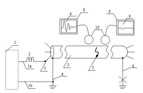
[0033] refer to figure 1 As shown, a method of locating the fault point of the cable using the shock oscillatory wave is carried out according to the following steps:
[0034] 1), the grounding output terminal 1b of the ordinary high-voltage shock pulse signal source 1 is connected to the grounding wire 4 at the beginning of the faulty cable 3 to be tested;
[0035] 2) The high-voltage output terminal 1a of the ordinary high-voltage shock pulse signal source 1 is connected to one end of the high-voltage resonant reactor 2;
[0036] 3) The other end of the high voltage resonant reactor 2 is connected to the fault phase 7 of the fault cable to be tested;
[0037] 4) Disconnect the terminal ground wire 6 of the faulty cable 3 to be tested;
[0038] 5) The ordinary high-voltage shock pulse signal source 1 applies a high-voltage shock pulse signal to the faulty cable 3 to be tested through the high-voltage resonant reactor 2, so that the fault point 5 forms an instantaneous short...
Embodiment 2
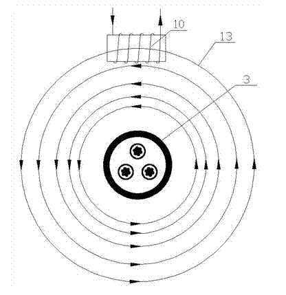
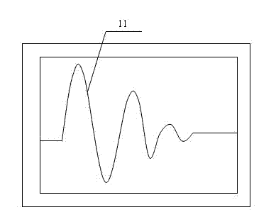
[0053] The magnetic field signal detection device 8 of the present invention can also be used to detect the cable path before the fault point. When the magnetic field signal induction receiving coil 10 is placed above the position of the cable to be tested, the amplitude of the waveform 11 is the largest, and then go forward along the ground , the detection device always displays waveform 11, if the detection device does not display waveform 11, it indicates that the cable path is skewed, and the direction of the cable path should be adjusted (or left or right). When the amplitude of waveform 11 is the largest, the magnetic field induction receiving coil 10 is on the ground. The path below it corresponds to the path of the underground cable.
PUM
 Abstract
Description
Claims
Application Information
 - R&D
- Intellectual Property
- Life Sciences
- Materials
- Tech Scout
- Unparalleled Data Quality
- Higher Quality Content
- 60% Fewer Hallucinations
Browse by: Latest US Patents, China's latest patents, Technical Efficacy Thesaurus, Application Domain, Technology Topic, Popular Technical Reports.
© 2025 PatSnap. All rights reserved.Legal|Privacy policy|Modern Slavery Act Transparency Statement|Sitemap|About US| Contact US: help@patsnap.com


