

OpenGL (open graphics library)-based inverted image display processing device and method
A reflection and display device technology, applied in image data processing, 3D image processing, instruments, etc., can solve the problems of inflexible production process, heavy artist workload, difficult to handle non-planar object models, etc., and achieve the change of fixed assembly line operation mode, good picture effect and fluency, high efficiency, flexibility and adaptability
- Summary
- Abstract
- Description
- Claims
- Application Information
AI Technical Summary
Problems solved by technology
Method used
Image

Examples
Embodiment Construction
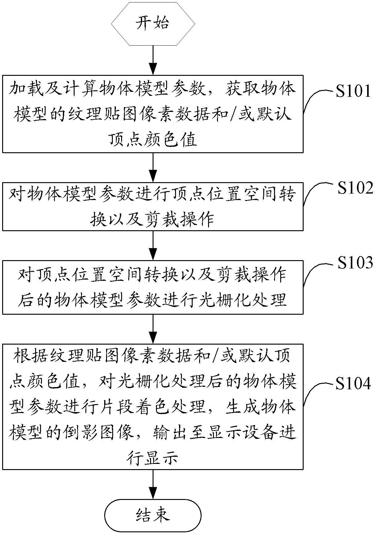
[0050]The solution of the embodiment of the present invention is mainly: by loading and calculating the object model parameters by the CPU, obtaining the texture map pixel data and / or the default vertex color value of the object model; and then performing the vertex position space conversion and clipping operation on the object model parameters by the GPU in turn , rasterization processing and fragment coloring processing, generate a reflection image of the object model, and output it to a display device for display. The reflection effect of the object model is realized through parameter control, and the simulated reality is more realistic. The hazy gradient fade does not depend on the original texture image of the object model, nor does it depend on the format of the original texture image, the number of color channels, and the length of color bytes to save storage. Space, and reduce the amount of CPU operations and memory usage.
[0051] The invention is realized through Ope...
PUM
 Abstract
Description
Claims
Application Information