
High-shear device and method of high shearing

A high-shear and screw technology, applied in the field of high-shear devices, can solve the problems of high-shear efficiency reduction, inability to apply constant shear stress, etc.

Inactive Publication Date: 2012-01-04
NIIGATA MACHINE TECHNO CO LTD
View PDF1 Cites 5 Cited by
  • Summary
  • Abstract
  • Description
  • Claims
  • Application Information

AI Technical Summary

Problems solved by technology

However, by providing the tapered surface 102a, a constant shearing stress cannot be applied to the high-sheared resin, thereby reducing the high-shearing efficiency.

Method used


Image

  • High-shear device and method of high shearing
  • High-shear device and method of high shearing
  • High-shear device and method of high shearing

Examples


Embodiment

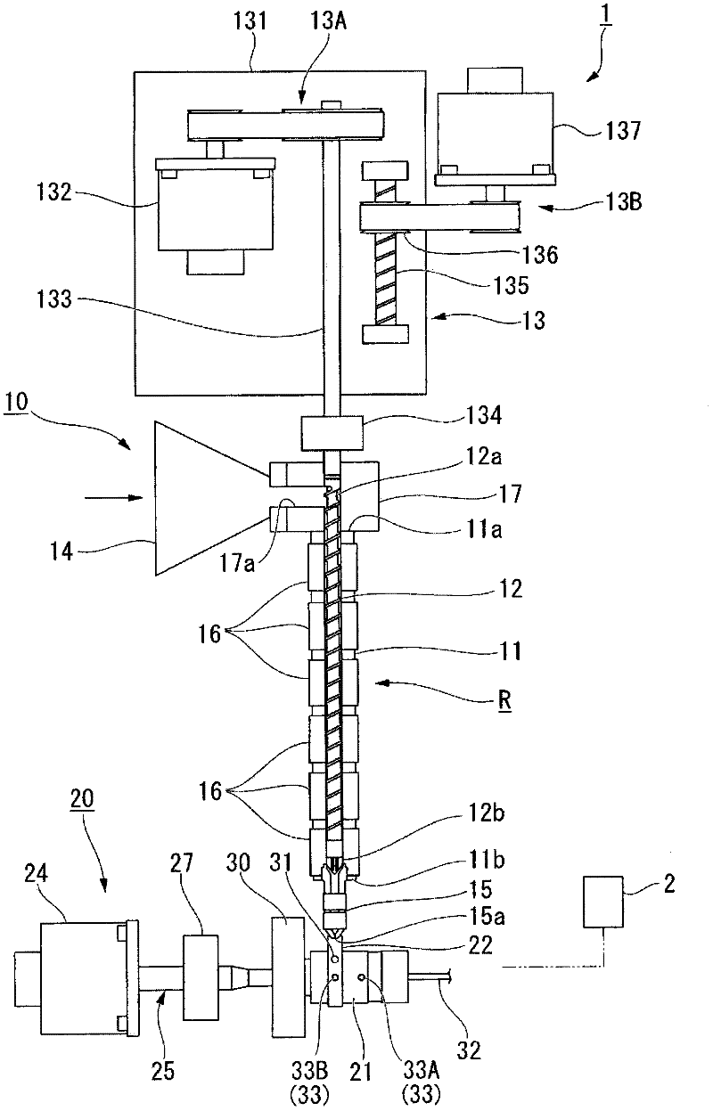
[0106] In the example, using figure 1 In the high-shear device 1 shown, the polymer hybrid resin obtained by mixing polycarbonate (PC) and acrylic acid (PMMA) at a ratio of 8:2 is nano-dispersed using a high-shear unit to produce a polymer hybrid resin. Extrusion.

[0107] First, in the plasticizing unit, the temperature of the heating cylinder 11 is set at 220° C., and the plasticizing screw 12 is rotated at a low speed of 300 rpm or less to plasticize and melt the above-mentioned resin to produce uniformly kneaded molten resin.

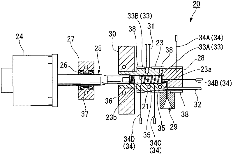
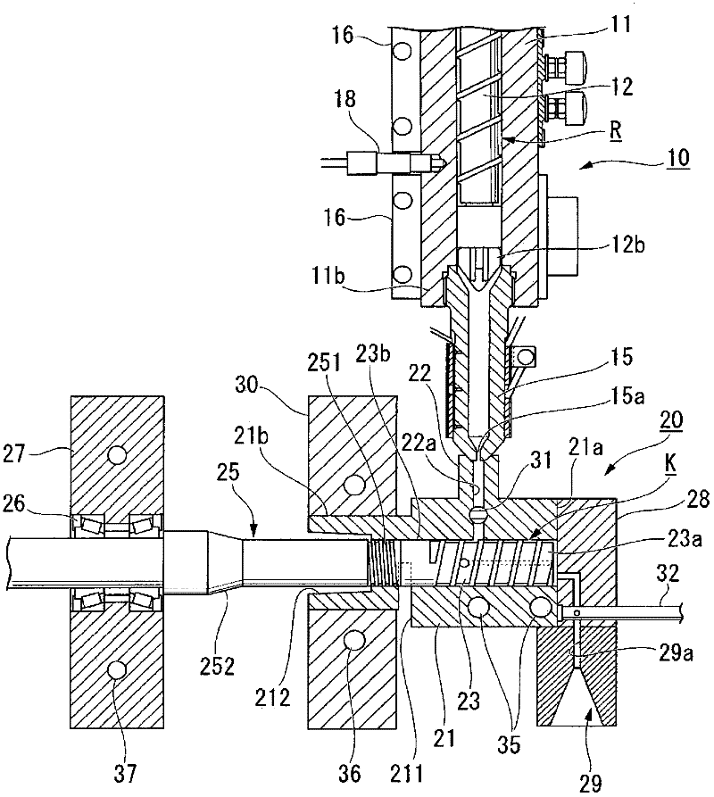
[0108] Inject the molten resin into the heating cylinder 21 of the high-shear unit 20, using a screw diameter of 28 mm, a pitch of 11 mm, a width of the screw thread (screw crest) of 2 mm, a diameter of the return hole of 2.5 mm, and an effective length of the screw (from the front end of the screw to the return) The distance from the center of the discharge port of the hole) to the internal return type screw 23 of 50 mm, the screw speed is 2500 rpm...


PUM


Abstract

A high-shear melt-kneader includes a high-shear unit (20) having an internal feedback-type screw (23) configured to apply high-shear stress to a melted resin, resin pressure sensors (33) for configured to detect a front portion resin pressure in the vicinity of an inlet of the internal feedback-type screw and a rear portion resin pressure in the vicinity of an outlet, and a control device configured to appropriately control a material supplying amount, a material temperature, a kneading time, and a screw rotation speed according to pressure values detected by the sensors. The control device controls the conditions such that waveforms with the lapse of time of the front and rear portion resin pressures are similar to each other and show variation to a steady state after formation of a predetermined peak value, and the front and rear portion resin pressures form a predetermined pressure difference with the lapse of time. According to the high-shear melt-kneader, it is possible to improve high-shear efficiency, increase precision of nano dispersion of a material, and stably and finely disperse / mix internal structures of immiscible polymer blend-based, polymer / filler-based and polymer blend / filler-based materials to a nano level.

Description

technical field [0001] The present invention relates to a high shear device and high shear method for use in high shearing of materials such as immiscible polymer blends, polymer / fillers, and polymer / filler blends. , to disperse and mix the internal structures of these materials at the nanoscale. This application claims the priority based on Japanese Patent Application No. 2009-25088 for which it applied to Japan on February 5, 2009, The content is used here. Background technique [0002] A high-shear machine is known that produces a dispersed phase with a size of tens of nanometers without adding additional additives such as solubilizers for mixed materials that are incompatible with each other (immiscible) under an electrostatic field. Polymer coextrusion (for example, refer to Patent Document 1). [0003] Patent Document 1 discloses a structure in which, in a high-shear machine equipped with an internal return type high-shear screw, the high-shear screw is rotated at a ...

Claims


Application Information

Patent Timeline
IPC IPC(8): B29B7/28B29B7/88B29B7/74B29B7/10
CPCB29B7/88B29B7/14B29B7/28B29B7/726B29B7/728B29B7/823B29B7/826B29B7/90B29B7/10B29B7/74
Inventor 清水博李勇进吉泽行雄高桥孝之丰岛健一
Owner NIIGATA MACHINE TECHNO CO LTD
Learn More