Optical connector protecting assembly of optical adapter and installing box of optical adapter

An adapter and installation box technology, applied in the field of communication, can solve problems such as inconvenient installation, high cost, and complex structure, and achieve the effects of convenient operation, protection of optical fiber heads, and simple structure

Inactive Publication Date: 2012-01-04
李静
View PDF7 Cites 1 Cited by
  • Summary
  • Abstract
  • Description
  • Claims
  • Application Information

AI Technical Summary

Problems solved by technology

[0005] The purpose of the embodiments of the present invention is to provide an optical adapter optical port protection assembly and an optical adapter installation box, which can be assembled with a relatively simple structure to form a low-cost and fast-installed assembly that prevents the o...

Method used


Image

  • Optical connector protecting assembly of optical adapter and installing box of optical adapter
  • Optical connector protecting assembly of optical adapter and installing box of optical adapter
  • Optical connector protecting assembly of optical adapter and installing box of optical adapter

Examples


Embodiment 1

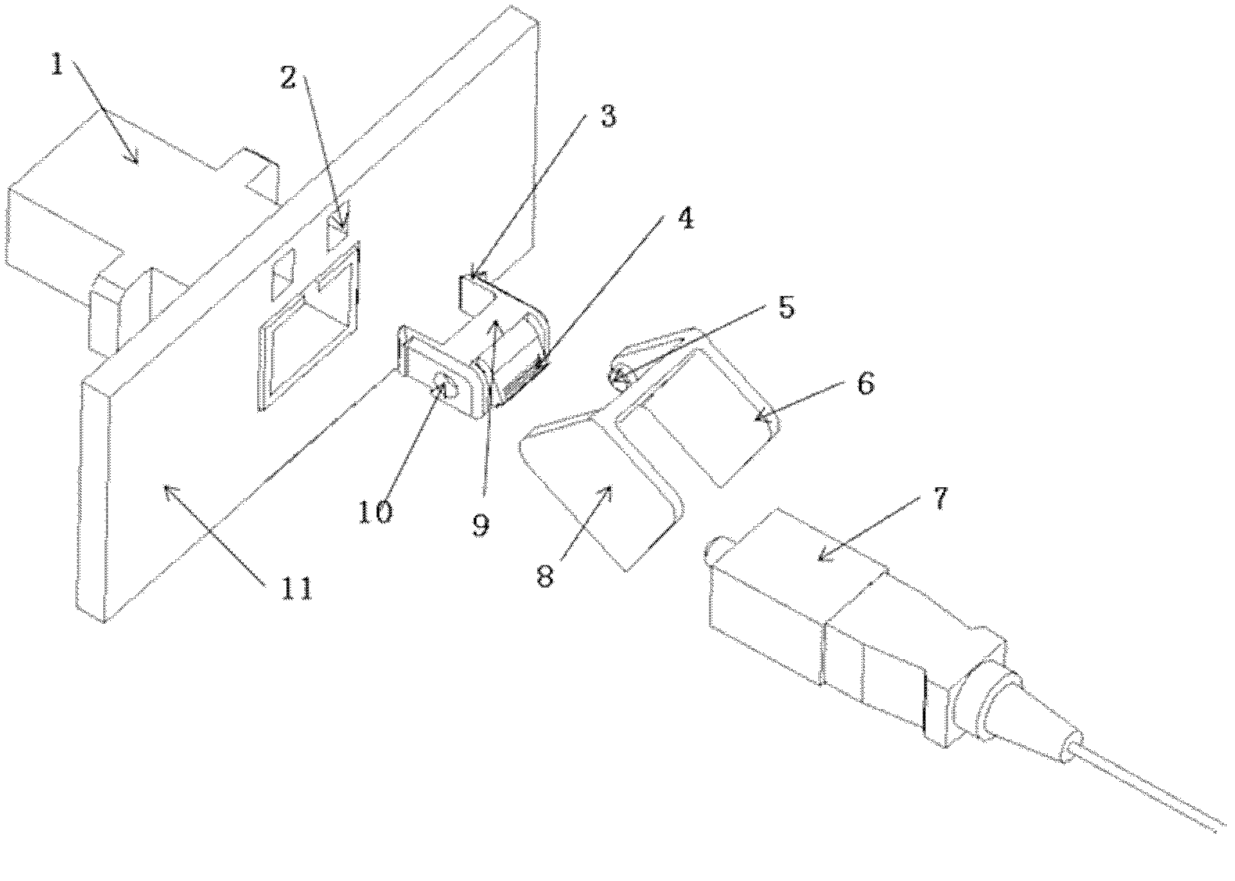
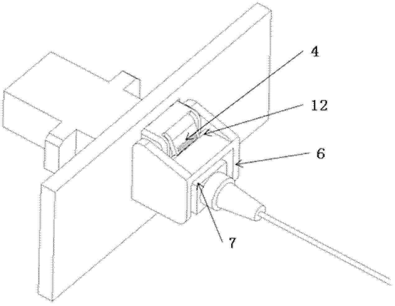
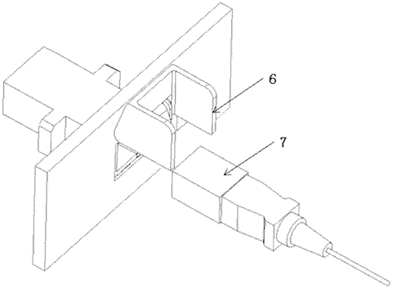
[0025] This embodiment provides an optical adapter optical port protection assembly, which is used on the optical adapter installation box to protect the optical fiber head and prevent the optical fiber head from being pulled out from the optical adapter at will, such as figure 1 As shown in the structural diagram of the optical adapter optical port protection component, the protection component includes: mounting base and sheath;

[0026] Wherein, the mounting base is provided with a mounting end and a limit piece, and the mounting end allows the mounting base to be attached to an attachment. For example, the protective component can be fixed on the communication equipment panel through the mounting end or the protective component can be snapped through the mounting end to make the protection The component is installed on the panel of the communication equipment. The structure of the installation end can be composed of two elastic protrusions that are kept at a certain distanc...

Embodiment 2

[0036] This embodiment provides an optical adapter installation box, which is formed on the basis of the protective assembly in the first embodiment above, and can prevent the optical fiber head inserted into the optical port of the optical adapter from being pulled out at will. Such as Figure 4 As shown in the structural diagram of the optical adapter installation box, the optical adapter installation box includes: a box body, an optical adapter, and the optical adapter optical port protection assembly given in the first embodiment above; wherein,

[0037] The optical adapter 22 is arranged in the box body, and the optical port of the optical adapter 22 is arranged on the panel 21 of the box body;

[0038]The optical adapter optical port protection assembly 23 is fixedly arranged outside the box, and is arranged at the optical port of the optical adapter 22 on the box body panel 21, that is, the opening groove of the sheath of the optical adapter optical port protection asse...


PUM


Abstract

The invention provides an optical connector protecting assembly of an optical adapter and an installing box of an optical adapter, which belong to communication field. The assembly comprises an installing base and a protecting sleeve. The installing base comprises an installing end and a spacing sheet. The protecting sleeve is provided with an open groove capable of containing an optical fiber head, and is movably disposed on the installing base and can move to a first or second position along the installing base. When the protecting sleeve is in the first position, the spacing sheet separates from the protecting sleeve. When the protecting sleeve is in the second position, the spacing sheet is clamped on the protecting sleeve, enabling the protecting sleeve and the installing base to be fixed and lock the optical fiber head in the protecting sleeve. The protecting assembly is simple in structure and convenient in operation and is free of bolts. After the optical fiber head is installed in the optical adapter, a rotating protection sleeve is clamped by the spacing sheet on the installing base, and the protection sleeve conducts a spacing on the optical fiber head. As the protection sleeve cannot be opened after being clamped, the optical fiber head cannot be taken off from the optical adapter at will, effectively protecting the optical fiber head.

Description

technical field [0001] The invention relates to the communication field, in particular to an optical adapter optical port protection component and an optical adapter installation box. Background of the invention [0002] In the FTTx (Fiber To The x, fiber to x) solution, the ONT (Optical Network Terminal, optical network terminal) is used as a terminal device and placed in the user's home, and the user can plug and unplug the optical fiber at will (especially children). It can cause personal injury (laser damages human eyes), and it is also easy to affect the quality of optical signals. Therefore, most operators require that users be restricted from plugging and unplugging optical fibers. [0003] A kind of scheme of present prior art is to make the optical port of optical adapter shrink inward, promptly the box body of optical adapter is opened gap, adds a plastic cover, and plastic cover is installed with screw, is inserted and pulled out arbitrarily to protection optical...

Claims


Application Information

Patent Timeline
IPC IPC(8): G02B6/38G02B6/36
CPCG02B6/3825G02B6/3849
Inventor 陈世荣柯江怀司广福龙彦
Owner 李静
Why Eureka
Try Eureka