Suspension device for gearshaft carburizing and quenching

A technology of carburizing quenching and hanging devices, which is applied in the direction of quenching devices, furnace types, furnaces, etc., can solve the problems of fast cooling speed, slow cooling speed, and low service life, and achieve small quenching deformation, small deformation of workpieces, and easy use long life effect

Inactive Publication Date: 2012-01-11
XIANGTAN ELECTRIC MFG
View PDF1 Cites 7 Cited by
  • Summary
  • Abstract
  • Description
  • Claims
  • Application Information

AI Technical Summary

Problems solved by technology

Since there is a column in the center of the combination device, and a gasket is placed on the column, a large amount of heat is accumulated in the center of the combination device. When quenching, the cooling speed is slow due to the poor heat dissipation conditions in the center of the combination device. The heat dissipation conditions of the outer circle of the combination device It is good and the cooling speed is fast, which causes the cooling speed of the part near the outer circle of the gear shaft to be different from that near the center, resulting in thermal stress and structural stress, so that the journal part of the gear shaft is affected by the thermal stress and structural stress during quenching. If it exists, the tooth direction and radial deformation of the tooth portion will occur. After this deformation is greater than the amount of wear left on the tooth portion, the tooth portion will not be able to be ground and will be scrapped, and the service life of this device is low.

Method used


Image

  • Suspension device for gearshaft carburizing and quenching
  • Suspension device for gearshaft carburizing and quenching
  • Suspension device for gearshaft carburizing and quenching

Examples


Embodiment Construction

[0010] The present invention will be further described below in conjunction with the accompanying drawings and embodiments.

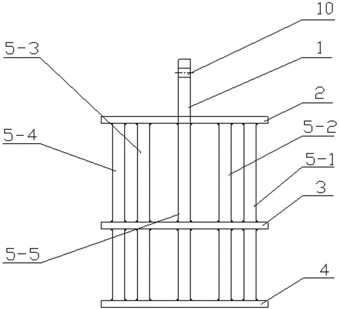
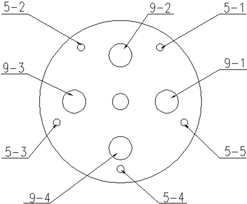
[0011] With reference to the accompanying drawings, this embodiment consists of a hanging column 1, an upper support plate 2, a lower support plate 3, a bottom plate 4, and five identical columns I 5-1, II 5-2, III 5-3, and IV 5- 4. Upright column Ⅴ 5-5; said hanging column 1 passes through the center hole of upper support plate 2 and lower support plate 3 and is welded and fixed with upper support plate 2, lower support plate 3 and bottom plate 4; The top is provided with a hoisting hole 10; the column I 5-1, column II 5-2, column III 5-3, column IV 5-4, and column V 5-5 pass through the upper support plate 2 and the lower support plate 3 respectively. Holes evenly distributed around the circumference, and welded with the upper support plate 2, the lower support plate 3, and the bottom plate 4, the column I 5-1, the column II 5-2, the column III 5-3, t...


PUM


Abstract

The invention relates to a suspension device for gearshaft carburizing and quenching. The device comprises a hanging pillar, an upper support plate, a lower support plate, a base plate and five identical vertical columns; the hanging pillar passes through the center openings of the upper support plate and the lower support plate, and is fixed with the upper support plate, the lower support plate and the base plate through welding, and a hoisting opening is positioned at the top of the hanging pillar; the five vertical columns respectively pass through openings circumferentially and uniformly distributed on the upper support plate and the lower support plate, and are fixed with the upper support plate, the lower support plate and the base plate through welding, with the tops of the five vertical columns flush with the upper support plate, and the diameters of the five vertical columns equal to the diameter of the hanging pillar; the upper support plate is provided with five circumferentially and uniformly distributed through holes for placing the gearshaft, and is also equipped with five oil holes uniformly distributed on two circumferences of different diameters; the lower support plate and the upper support plate have the same structure; and the base plate is provided with four circumferentially and uniformly distributed oil holes. Employment of the device provided in the invention for carburizing and quenching a gearshaft can control the gearshaft deformation after carburizing and quenching, thus reducing the rejection rate of gearshafts.

Description

technical field [0001] The invention relates to a gear shaft carburizing and quenching tool, in particular to a gear shaft carburizing and quenching hanging device. Background technique [0002] At present, the hanging device used in the carburizing and quenching of the gear shaft is a combination device. The center of the combination device is a column, and the lower end of the column is welded with a circular base. The column is covered with two triangular brackets with holes in the center. It is an upper triangle bracket and a lower triangle bracket, which are used to place the upper and lower layers of gear shafts; the triangle brackets are separated by washers to adjust the distance between the two triangle brackets, and a circular support plate with holes is placed on the bracket. When working, insert the gear shaft into the hole of the support plate, use the steps of the gear shaft, place it on the support plate, and carry out carburizing in the furnace. The material...

Claims


Application Information

Patent Timeline
Patent Type & Authority Applications(China)
IPC IPC(8): C23F17/00C21D9/32C21D1/62C23C8/20
Inventor 李立元徐伟文彭宗强杨艳芳
Owner XIANGTAN ELECTRIC MFG
Why Eureka
Try Eureka