Oil conveying pipeline on-line density measuring device

A technology for density measurement and oil pipelines, applied in pipeline systems, mechanical equipment, gas/liquid distribution and storage, etc., can solve problems such as no sewage system, pipeline cathodic protection current loss, density measurement operation and accuracy impact, etc., to achieve Save floor space and operating room, avoid cathodic protection current loss, reduce equipment investment and construction costs

Active Publication Date: 2012-01-11
BC P INC CHINA NAT PETROLEUM CORP +1
View PDF5 Cites 1 Cited by
  • Summary
  • Abstract
  • Description
  • Claims
  • Application Information

AI Technical Summary

Problems solved by technology

[0003] The disadvantages of this density measurement method are: 1. This method does not carry out online compensation of temperature and pressure for density measurement, which affects the accuracy of density measurement; 2. Due to the low cleanliness of the pipeline medium, impurities and iron filings contained in it The sampling pump is often blocked, resulting in failure and damage of the sampling pump, so that the continuous detection of the online density cannot be realized; 3. Using the bypass sampling method to measure the density is easy to cause thermal expansion of the pipeline and overpressure, thereby damaging the bypass measurement pipeline and measurement equipment; 4. The online verification of the density meter cannot be realized; 5. Since the bypass measurement method is directly connected to the main process pipeline, it is easy to cause the loss of the cathodic protection current of the pipeline, and the cathodic protection current is also likely to affect the operation and accuracy of the density measurement; 6. Without the monitoring of the instrument system, it is impossible to realize the detection and control of the measurement circuit in the SCADA system; 7. Without the sewage system, it is impossible to realize the maintenance of the equipment; 8. Without heat preservation and mixing heat, it is impossible to realize the open-air setting of the measurement circuit

Method used


Image

  • Oil conveying pipeline on-line density measuring device
  • Oil conveying pipeline on-line density measuring device

Examples


Embodiment

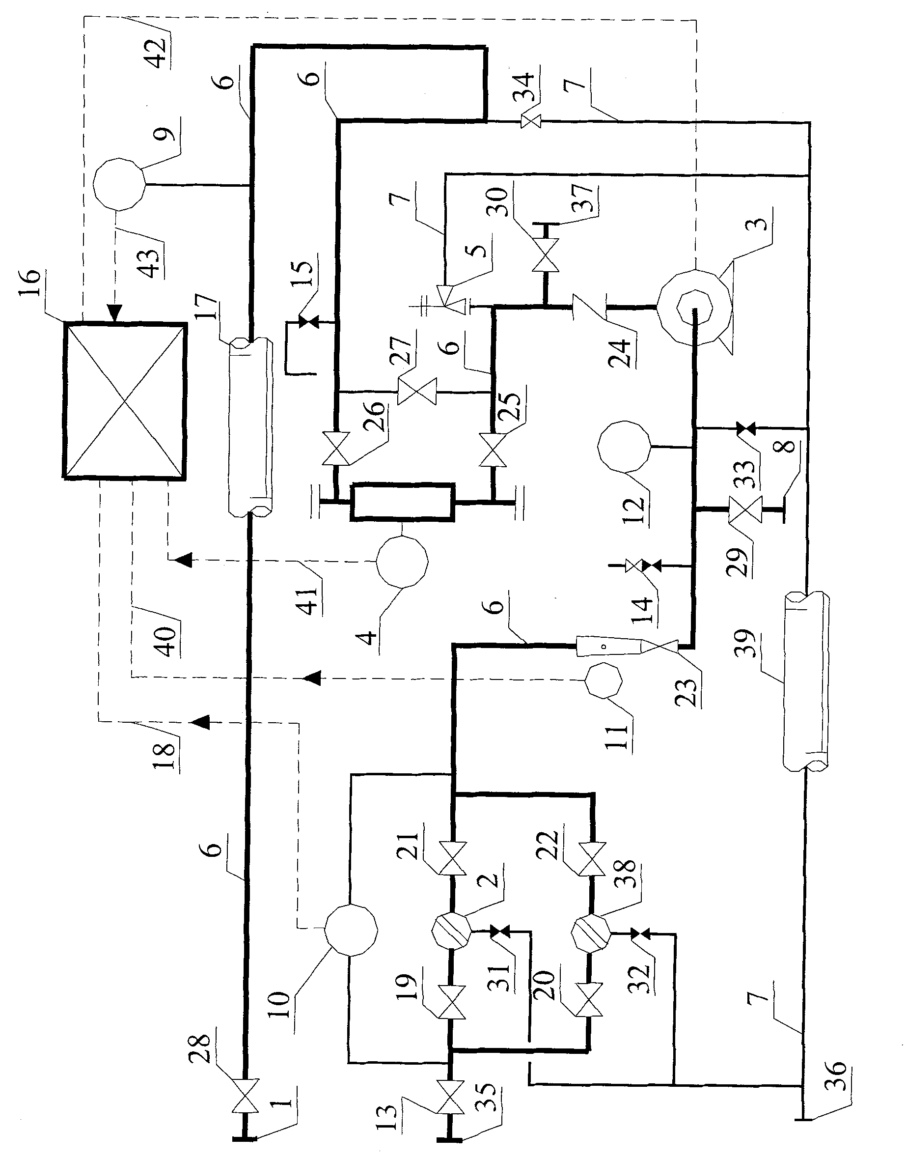
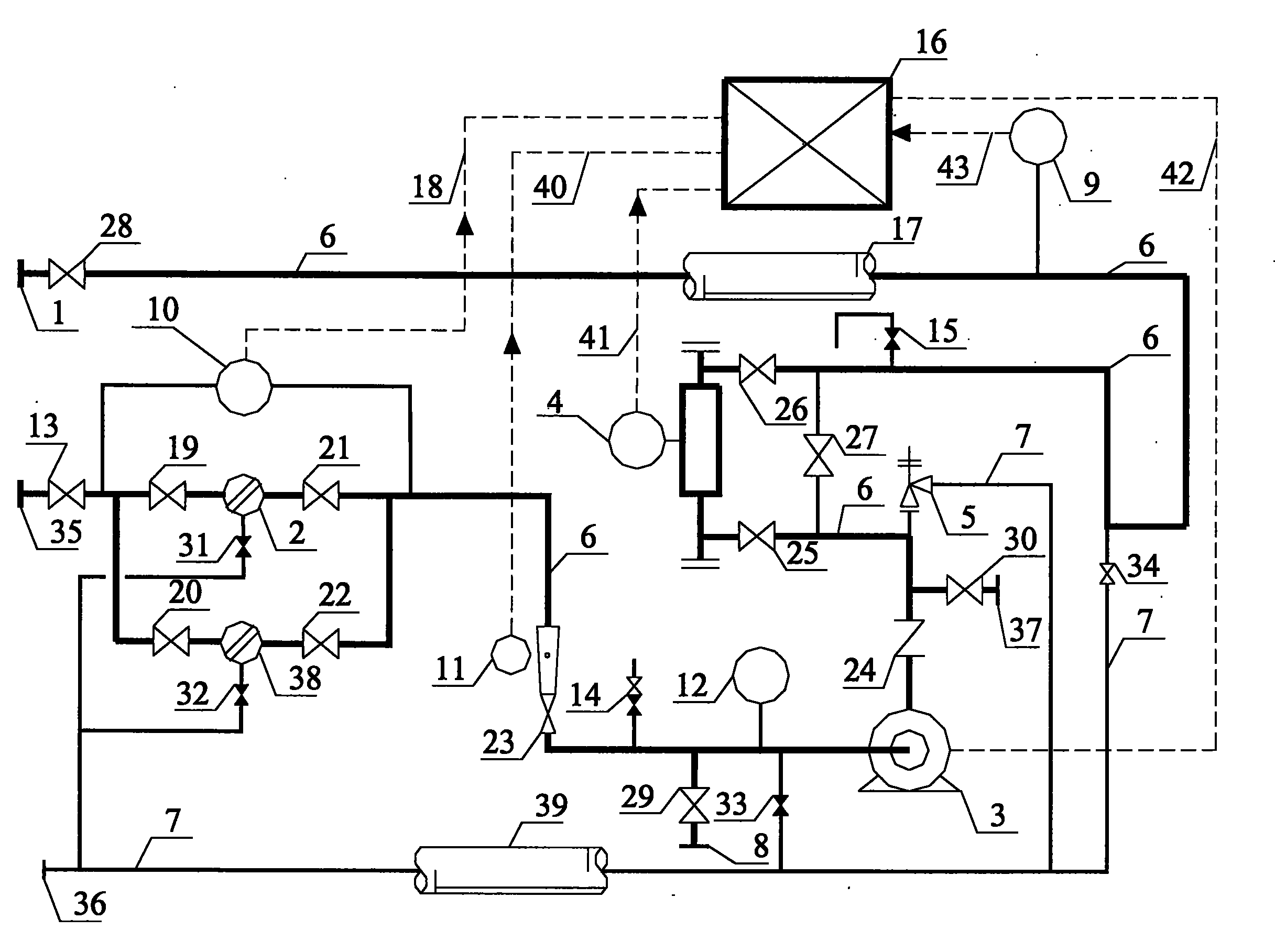
[0043] Embodiment. This example is an online density measuring device used in the Lanzhou-Zhengzhou-Changsha refined oil pipeline engineering test. The composition of the online density measuring device of the oil pipeline is as follows: figure 1 As shown, it consists of flange (1) 1, flange (2) 35, magnetic filter (1) 2, magnetic filter (2) 38, sampling pump 3, online density meter 4, thermal expansion safety valve 5, process supervisor Line 6, sewage pipeline 7, online verification port (1) 8, online verification port (2) 37, intelligent pressure transmitter 9, intelligent differential pressure transmitter 10, flow switch 11, local pressure gauge 12, multiple Process valve, manual sampling valve 14, exhaust valve 15, instrument junction box 16, constant temperature electric mixing heat and heat preservation 17, and multiple instrument cables. A bypass pipeline is set on the pipeline to be tested, and a section of the main process line 6 for testing is connected in series on...


PUM


Abstract

The invention discloses an oil conveying pipeline on-line density measuring device. A process main pipeline [6] of a constant-temperature electric heat tracing and thermal insulation device [17] is connected in series to a pipeline to be tested through a flange (1) [1] and a flange (2) [35] at the two outer ends, and is sequentially provided with parallel filter (1) [2] and filter (2) [38] and a differential pressure transmitter [10], a flow switch [11], a serial process valve (6) [23], a bypass manual sampling valve [14], a bypass on-line verification port (1) [8], a bypass in-situ pressure gauge [12], a bypass drainage pipeline [7], a sampling pump [3], a serial process valve (7) [24], a bypass on-line verification port (2) [37], a bypass thermal expansion safety valve [5], an on-line densimeter [4], a bypass exhaust valve [15], a bypass drainage pipeline [7] and an intelligent pressure transmitter [9] which are arranged in front of and behind the filters from the inlet end; and an instrument junction box [16] is connected with an SCADA (Supervisory Control And Data Acquisition) system.

Description

technical field [0001] The invention is an online density measuring device for an oil pipeline. Involved in the field of quality inspection and pipeline system technology. Background technique [0002] For the on-line density measurement of oil pipelines, the previous technological method is to draw a bypass on the main oil pipeline, set a sampling pump and a density meter on the bypass, and then merge the bypass into the main pipeline. [0003] The disadvantages of this density measurement method are: 1. This method does not carry out online compensation of temperature and pressure for density measurement, which affects the accuracy of density measurement; 2. Due to the low cleanliness of the pipeline medium, impurities and iron filings contained in it The sampling pump is often blocked, resulting in failure and damage of the sampling pump, so that the continuous detection of the online density cannot be realized; 3. Using the bypass sampling method to measure the density ...

Claims


Application Information

Patent Timeline
Patent Type & Authority Applications(China)
IPC IPC(8): F17D5/00
Inventor 聂中文邓东花张文伟姜兆昌胡协兰黄丽卢喆
Owner BC P INC CHINA NAT PETROLEUM CORP
Why Eureka
Try Eureka