Thermoelectricity-separating high-heat-conducting LED (light emitting diode) light source substrate

An LED light source, thermoelectric separation technology, applied in the direction of light source, light source fixed, point light source, etc., can solve the problems of limited thermal conductivity improvement, reduced voltage resistance, high thermal resistance, etc., to reduce contact thermal resistance and improve thermal conductivity. efficiency and cost reduction

Inactive Publication Date: 2012-01-11
WUXI TONGMING TECH
View PDF3 Cites 5 Cited by
  • Summary
  • Abstract
  • Description
  • Claims
  • Application Information

AI Technical Summary

Problems solved by technology

Recent studies have shown that the thermal conductivity of MCPCB can be improved by laminating highly conductive materials in the polymer insulating dielectric material of MCPCB, but it can only be increased to about 3~5W / mK, and the cost has increased a lot;
[0009] 2. Due to the use of metal substrates, in order to meet the requirements of safety regulations (creepage distance), the copper wire must be kept at a considerable distance from the edge of the printed circuit board, via holes, fixing (metal) screws, etc., for small lamps In terms of lighting, this often brings great obstacles to the safety requirements of lamps;
[0010] 3. In practical application, when MCPCB is stamped and divided, it will cause deformation of the polymer dielectric insulation layer on the edge of the board due to metal extension and deformation, which will reduce the withstand voltage performance and cause safety hazards;
[0011] 4. During use, the insulating layer of MCPCB may peel off from the metal substrate. Once peeled off, it will not be able to conduct heat smoothly, which will lead to rapid failure of the LED;
[0013] 6. At present, the metal substrate commonly used in MCPCB is aluminum. If the heat sink of the LED is directly in contact with the substrate, due to the material, there is a problem that it cannot be soldered.
[0014] In order to solve the problem of low thermal conductivity of FR4 PCB, Cree proposed the method of metal vias. The advantage is that when making PCB boards, metal via holes can be directly made on the PCB board, and metal cores can be embedded into metal vias. In the hole, it is easy to install and save cost, but its disadvantage is that due to the limitation of the processing conditions of the metal wire hole, the aperture is too small, and the heat of the thermal layer cannot be quickly conducted from the LED to the heat sink, so it must be placed on the PCB. Copper on top and bottom of the board
This method is not only costly, but also has a limited improvement in thermal conductivity, and at the same time brings great difficulties to pass the requirements of safety regulations.
[0015] The heat dissipation of high-power LEDs is mainly through the heat sink. The heat sink is usually non-conductive, and the two conductive pins are very thin due to the very thin gold wires used for connection, and the thermal resistance is very high, so they cannot play a role in heat dissipation. effect

Method used


Image

  • Thermoelectricity-separating high-heat-conducting LED (light emitting diode) light source substrate
  • Thermoelectricity-separating high-heat-conducting LED (light emitting diode) light source substrate
  • Thermoelectricity-separating high-heat-conducting LED (light emitting diode) light source substrate

Examples


Embodiment Construction

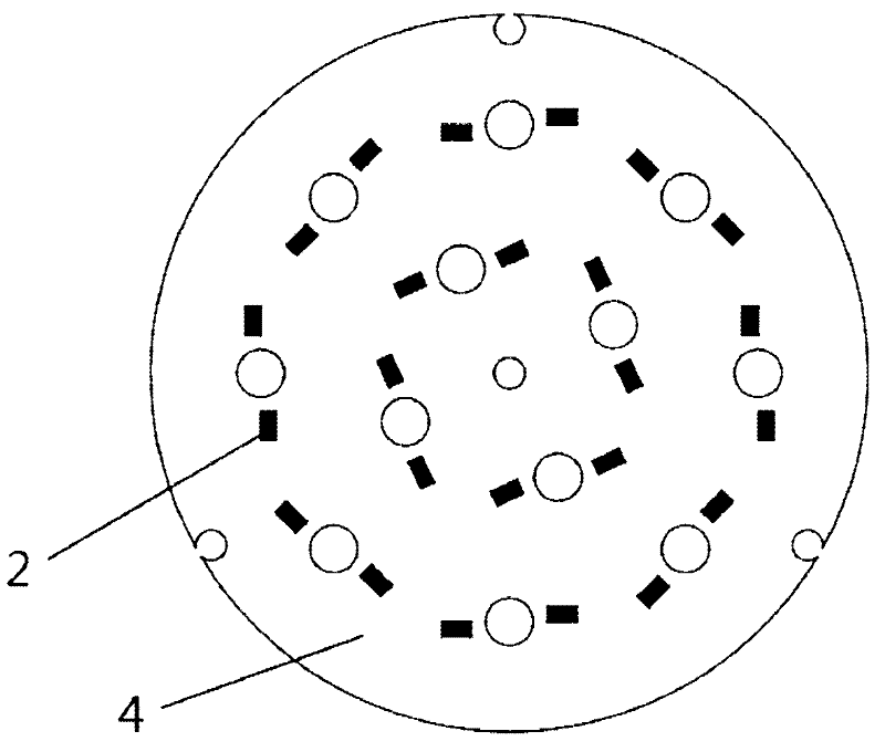
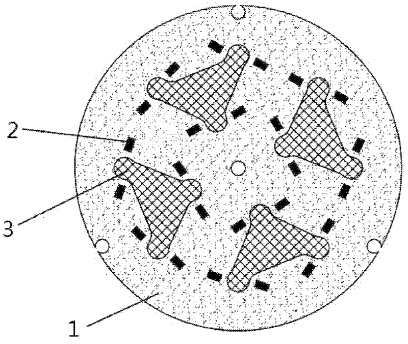
[0030] Such as figure 1 Shown is a LED light source board with thermoelectric separation and high thermal conductivity, including FR4 PCB substrate 1, said FR4 PCB substrate 1 is provided with LED conductive pin solder joints 2, said FR4 PCB is embedded with a heat-conducting metal plate 3, said heat-conducting The metal plate is insulated from the solder joints of the LED conductive pins. The heat-conducting metal plate can be an iron plate, an aluminum plate, a copper plate or a stainless steel plate with good heat-conducting effect. The preferred heat-conducting metal plate is copper plate.

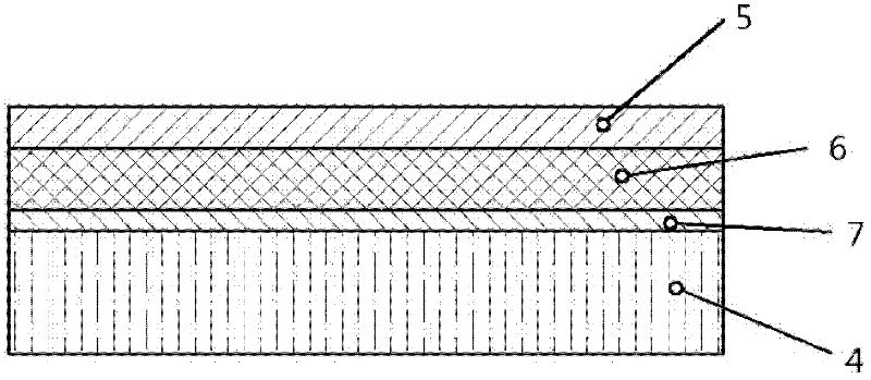
[0031] Solder the LED, FR4 PCB, and copper plate together by reflow soldering, and then fix the LED light source board on the radiator to form a whole. Use reflow soldering to directly solder the copper plate and the heat sink on the LED together with solder paste.

[0032] Since the thermal conductivity of the copper plate is 384W / m.K, this light source board can greatly reduce the...


PUM


Abstract

The invention discloses a thermoelectricity-separating high-heat-conducting LED (light emitting diode) light source substrate comprising an FR4 PCB (printed circuit board) substrate, wherein the FR4 PCB substrate is provided with an LED conductive pin soldered dot; and the LED light source substrate is characterized in that a conductive metal plate is inlaid on the FR4 PCB substrate, the conductive metal plate and the LED conductive pin soldered dot are insulated. The light source substrate can be used for greatly reducing the thermal resistance between an LED and a radiator; compared with an MCPCB (metal core PCB) light source substrate, the light source substrate provided by the invention has the advantages that the heat conductivity is improved by a hundred times or hundreds of times, the high voltage resistance of the LED light source substrate is consistent with that of the FR4 PCB substrate.

Description

technical field [0001] The invention relates to an LED light source board structure, in particular to an LED light source board with thermoelectric separation and high thermal conductivity. Background technique [0002] When LED light sources are used to make lighting fixtures, packaged LED particles need to be welded on a printed circuit board (hereinafter referred to as PCB). For LEDs, heat dissipation is extremely critical, because temperature has a great impact on the performance of LEDs such as light efficiency, light decay, and color drift, which directly affects their luminous efficiency and service life. The heat generated by the LED chip during use is transferred to the radiator through the heat sink and PCB. Therefore, the higher the thermal conductivity of the PCB, the better (that is, the lower the thermal resistance, the better). [0003] The most common PCB materials available include the following three: [0004] 1. Glass fiber epoxy resin PCB, according to...

Claims


Application Information

Patent Timeline
Patent Type & Authority Applications(China)
IPC IPC(8): F21V29/00F21V19/00F21Y101/02F21V29/89
Inventor 姚迎宪
Owner WUXI TONGMING TECH
Why Eureka
Try Eureka