A led integrated light source module

A technology of light source modules and LED chips, which is applied in the direction of light sources, point light sources, and semiconductor devices of light-emitting elements, etc., can solve the problem of low power density of LED integrated light source modules, single function of LED integrated light source modules, and low degree of intelligence. Advanced problems, to achieve the effect of increasing unit value, realizing high power, and realizing intelligence

Active Publication Date: 2018-08-24
FOSHAN EVERCORE OPTOELECTRONICS TECH
View PDF4 Cites 0 Cited by
  • Summary
  • Abstract
  • Description
  • Claims
  • Application Information

AI Technical Summary

Problems solved by technology

However, the LED and the LED integrated circuit driver, the first alternating current (AC) electrical terminal and the second AC terminal are all integrated on the same circuit board, resulting in low power density and low value per unit area of ​​the existing LED integrated light source module
Moreover, the area of ​​the circuit board is limited, and it is difficult to integrate other modules on the basis of the existing LED and LED integrated circuit driver, resulting in the single function of the existing LED integrated light source module and a low degree of intelligence

Method used


Image

  • A led integrated light source module
  • A led integrated light source module
  • A led integrated light source module

Examples


Embodiment Construction

[0029] In order to make the object, technical solution and advantages of the present invention clearer, the present invention will be further described in detail below in conjunction with the accompanying drawings. It is only stated here that the words for directions such as up, down, left, right, front, back, inside, and outside that appear or will appear in the text of the present invention are only based on the accompanying drawings of the present invention, and are not specific to the present invention. limited.

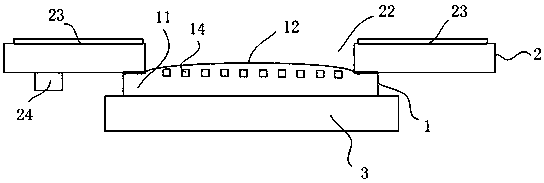
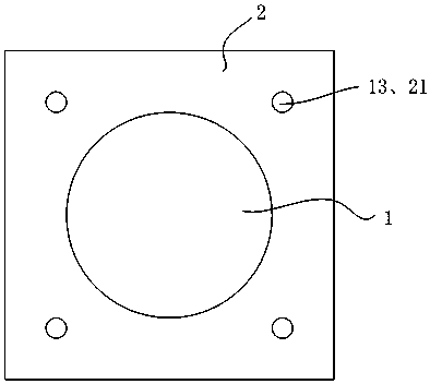
[0030] see figure 1 with figure 2 , figure 1 with figure 2 It shows the first embodiment of the LED integrated light source module of the present invention, which uses a COB light source as the LED light source, and at least includes: a COB light source 1, a driving board 2 arranged above the COB light source 1, and a drive board 2 arranged on the COB light source 1 The heat conducting plate 3 below.

[0031] Among them, COB (chip on board) is a highly int...


PUM


Abstract

The invention discloses an LED integrated light source module. The LED integrated light source module at least comprises a COB light source, a driving plate and a heat transfer plate, wherein the driving plate is arranged above the COB light source, and the heat transfer plate is arranged below the COB light source. The COB light source comprises a light source substrate and a light-emitting zone. A bonding pad is arranged on the light source substrate. One or more LED chips are arranged on the light-emitting zone. A through hole is formed in the position, corresponding to the light-emitting zone, of the driving plate. Light of the LED chips can penetrate out of the through hole. The driving plate is at least provided with a bonding pad, a driving circuit and a power module. The bonding pad of the driving plate corresponds to the bonding pad of the light source substrate. The driving plate and the light source substrate are connected through a welding piece or a connecting piece to form an integrated structure so that the LED chips can be electrically connected with the driving circuit. The power module can provide electric supply to the LED chips to be used as a power source. By the adoption of the LED integrated light source module, the structure is novel and simple, the cost is moderate, multiple functions are achieved, the integration degree is high, the unit area value is high, and the high intelligence and high power are achieved.

Description

technical field [0001] The invention relates to LED packaging technology, in particular to an LED integrated light source module. Background technique [0002] LED is the abbreviation of light-emitting diode, which can directly convert electrons into photons by inputting low-voltage current. In the course of years of development, LED has gradually gained popularity and has developed into the era of LED lighting. [0003] Since the LED is driven by a low-voltage constant current, many functional modules need to be added to support it during use. The functional module may be an input power module suitable for use by LEDs. This functional module occupies a certain volume, and there are two common methods: [0004] One is an ordinary LED module, which separates the LED and the input power module from each other, places them within a certain distance from each other, and transmits signals and energy through data lines. However, a plurality of LEDs are scattered and arranged, ...

Claims


Application Information

Patent Timeline
Patent Type & Authority Patents(China)
IPC IPC(8): F21V23/04F21V29/85H01L25/075F21Y115/10
CPCF21V23/003F21Y2101/00H01L25/075
Inventor 王孟源童存声朱思远董挺波
Owner FOSHAN EVERCORE OPTOELECTRONICS TECH
Why Eureka
Try Eureka