Turn on the bottom furnace and its renovation method

A rotary hearth furnace and rotary bottom technology, applied in furnaces, furnace components, lighting and heating equipment, etc., can solve problems such as uneven temperature distribution, inability to fully ensure the uniformity of temperature distribution in the furnace, and inability to set burners, etc. To achieve the effect of large combustion

Active Publication Date: 2021-10-22
CHUGAI RO CO LTD
View PDF13 Cites 0 Cited by
  • Summary
  • Abstract
  • Description
  • Claims
  • Application Information

AI Technical Summary

Problems solved by technology

[0011] Regarding the generation of the atmosphere in the furnace, in Patent Document 2, the distance from each of the plurality of burners to a single exhaust port is different, so there is a problem that the temperature distribution in the furnace is not uniform.
[0012] In Patent Document 4, there is a problem that adjacent regenerative burners are alternately combusted, so that the heat generated by the flame of the combustion mode burner is immediately absorbed by the adjacent exhaust mode burner. Attraction, resulting in the inability to obtain the energy saving effect, and the temperature distribution in the furnace is uneven
[0013] In addition, as in Patent Document 2 and Patent Document 4, if a plurality of burners are only arranged on the outer peripheral wall or around the cylindrical furnace wall, the agitation of the furnace gas in the furnace is insufficient, and the furnace gas cannot be sufficiently ensured. The subject of homogenization of internal temperature distribution
In addition, if the burners are installed only on the outer peripheral wall or around the furnace wall, there is also a problem that the number of burners that can ensure the necessary combustion amount cannot be installed in the surrounding space.

Method used


Image

  • Turn on the bottom furnace and its renovation method
  • Turn on the bottom furnace and its renovation method
  • Turn on the bottom furnace and its renovation method

Examples


Embodiment Construction

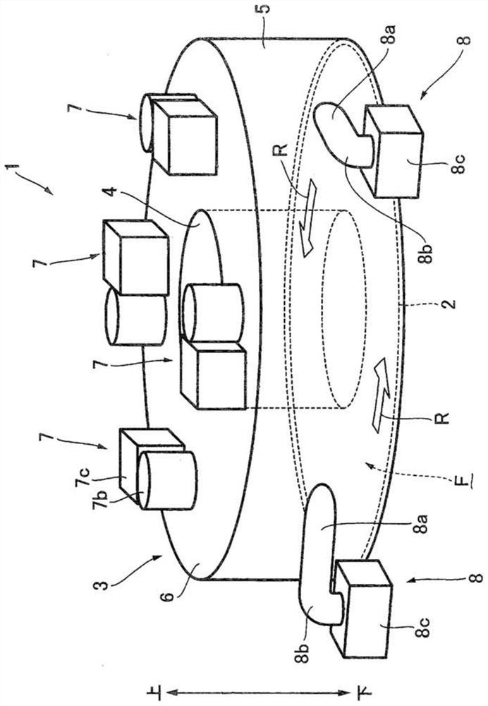
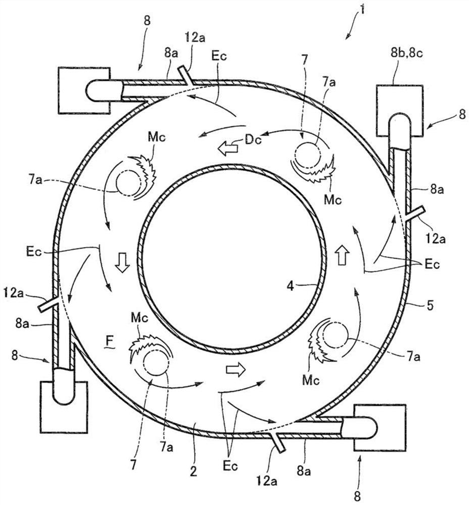
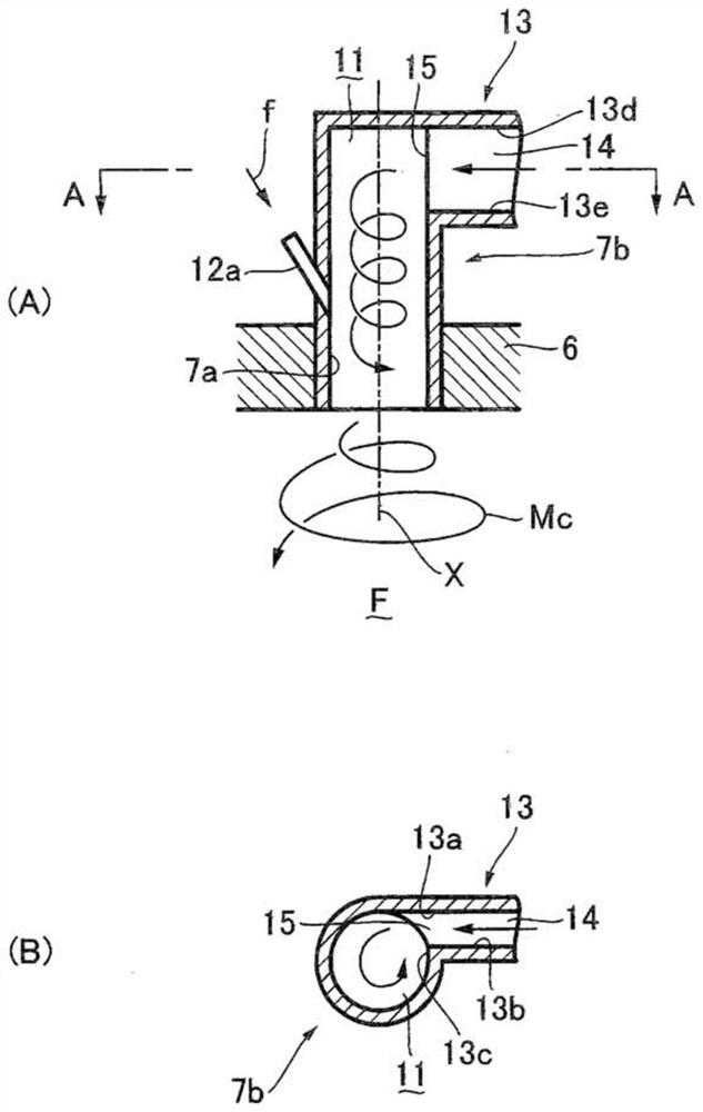
[0081] Hereinafter, a preferred embodiment of the rotary hearth furnace and its modification method of the present invention will be described in detail with reference to the drawings. figure 1 It is a perspective view briefly showing a preferred embodiment of the rotary hearth furnace of this embodiment, figure 2 is description figure 1 A top sectional view of the combustion state of the top burner in the rotary hearth furnace shown, image 3 yes applies to figure 1 An explanatory diagram illustrating the main parts of the top burner of the rotary hearth furnace shown, Figure 4 Yes figure 1 The equipment layout of the rotary hearth furnace shown is an explanatory diagram showing when the top burners are in the combustion mode and when the peripheral wall burners are in the exhaust mode, Figure 5 is description figure 1 The top sectional view of the combustion state of the peripheral wall burner in the shown rotary hearth furnace, Image 6 Yes figure 1 The shown equipm...


PUM


Abstract

The present invention provides a rotary hearth furnace and its modification method. The rotary hearth furnace is based on the use of regenerative burners, and can fully exert its energy-saving effect while improving the agitation of the furnace gas in the furnace to make the furnace The internal temperature distribution is uniform, and the top can be used to increase the installation space of the burner, and the number of burners that can be installed can be increased to ensure a larger combustion volume than before. In the rotary hearth furnace (1) provided with the rotary hearth (2) in the furnace F surrounded by at least the top (6) and the cylindrical outer peripheral wall (5), the top is equipped with The regenerative top burner (7) installed in the outer peripheral wall is equipped with a regenerative peripheral wall burner ( 8).

Description

technical field [0001] The present invention relates to a rotary hearth furnace and a modification method thereof. The rotary hearth furnace is based on the use of a regenerative burner and can fully exert its energy-saving effect while improving the agitation of the furnace gas in the furnace so that the temperature in the furnace can be reduced. The distribution is uniform, and the number of burners that can be set can be increased by proper arrangement of the burners to ensure sufficient combustion. Background technique [0002] Conventionally, the "rotary hearth furnace" of Patent Document 1 is known as an invention showing a rotary hearth furnace. In addition, for such a rotary hearth furnace, "raw material agglomerates for production of reduced iron" of Patent Document 2 is known regarding generation of atmosphere in the furnace. In Patent Document 2, a plurality of burners are arranged on the outer peripheral wall of the rotary hearth furnace, flames are generated to...

Claims


Application Information

Patent Timeline
Patent Type & Authority Patents(China)
IPC IPC(8): F27B3/20
CPCF27B3/205Y02E20/34F27B3/06F27D99/0033
Inventor 河本祐作川端健介
Owner CHUGAI RO CO LTD
Why Eureka
Try Eureka