Separator type heat exchange method and separator type heat exchange device

A heat exchange device and clapboard-type technology, which is applied in combustion methods, lighting and heating equipment, and indirect carbon dioxide emission reduction, can solve the problems of low energy utilization rate and low heat exchange efficiency of combustion furnaces, and improve energy utilization High efficiency, low exhaust gas temperature and novel structure

Inactive Publication Date: 2012-01-11
陈立德
View PDF4 Cites 2 Cited by
  • Summary
  • Abstract
  • Description
  • Claims
  • Application Information

AI Technical Summary

Problems solved by technology

[0004] The invention solves the technical problem of low energy utilization rate and low heat exchange efficiency of the combustion furnace in the prior art, and provides a partition type heat exchange method and a partition type heat exchange device, which utilizes the waste gas discharged from the combustion furnace to affect the combustion air Preheat and adopt a new heat exchange method to improve heat exchange efficiency

Method used


Image

  • Separator type heat exchange method and separator type heat exchange device
  • Separator type heat exchange method and separator type heat exchange device
  • Separator type heat exchange method and separator type heat exchange device

Examples


Embodiment 1

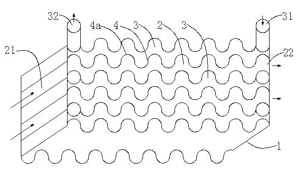
[0030] like figure 1 As shown, the baffle-type heat exchange device of this embodiment includes a housing 1, and at least two baffles 4 are fixed side by side at intervals in the housing 1, and the two sides of each of the baffles 4 are respectively used for passage of low temperature The low-temperature passage 2 for the medium and the high-temperature passage 3 passing through the high-temperature medium, and each low-temperature passage 2 is adjacent to the corresponding high-temperature passage 3 through a partition 4 . The partition plate 4 is formed with staggered protruding heat conduction surfaces 4a protruding toward both sides of the partition plate 4 respectively; the housing 1 is provided with a low-temperature passage inlet 21 and a low-temperature passage outlet 22 connected to each low-temperature passage 2, and connected with each low-temperature passage. A high-temperature channel inlet 31 and a high-temperature channel outlet 32 ​​connected to the high-temper...

Embodiment 2

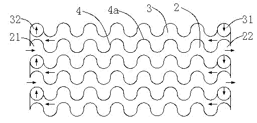
[0034] like figure 2 As shown, the baffle-type heat exchange device of this embodiment includes a housing 1, and at least two baffles 4 are fixed side by side at intervals in the housing 1, and the two sides of each of the baffles 4 are respectively used for passage of low temperature The low-temperature passage 2 for the medium and the high-temperature passage 3 passing through the high-temperature medium, and each low-temperature passage 2 is adjacent to the corresponding high-temperature passage 3 through a partition 4 . The partition plate 4 is formed with staggered protruding heat conduction surfaces 4a protruding toward both sides of the partition plate 4 respectively; the housing 1 is provided with a low-temperature passage inlet 21 and a low-temperature passage outlet 22 connected to each low-temperature passage 2, and connected with each low-temperature passage. A high-temperature channel inlet 31 and a high-temperature channel outlet 32 ​​connected to the high-tempe...

Embodiment 3

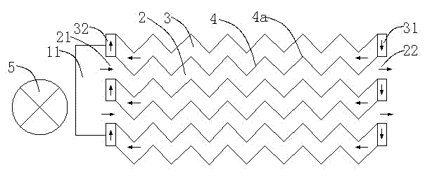
[0039] like Figure 4 and Figure 5 As shown, this implementation is a further improvement on the low-temperature channel inlet 21 and the low-temperature channel outlet 22 , as well as the high-temperature channel inlet 31 and the high-temperature channel outlet 32 ​​on the basis of the above two embodiments. The low-temperature channel inlet 21 and the high-temperature channel outlet 32 ​​are located side by side at one end of the housing 1 , and the low-temperature channel outlet 22 and the high-temperature channel inlet 31 are located side by side at the other end of the housing 1 .


PUM


Abstract

The invention discloses a separator type heat exchange method and a separator type heat exchange device, which comprise at least two low temperature passageways and at least two high temperature passageways, wherein heat conducting separators are arranged between the low temperature passageways and the high temperature passageways, and the separators are provided with concave heat conducting faces which face the low temperature passageways and the high temperature passageways and are used for increasing molecular collision probability; high temperature passageway inlets of the high temperature passageways are connected with an air outlet of a combustion furnace and hot waste gas generated by the combustion furnace is exhausted through high temperature passageway outlets of the high temperature passageways; and combustion supporting air is input through low temperature passageway inlets of the low temperature passageways, low temperature passageway outlets are connected with an air inlet of the combustion furnace, and the combustion supporting air enters the combustion furnace through the low temperature passageway outlets. The separator type heat exchange device has a novel structure and an ingenious design, the design idea of the traditional heat exchange device is changed, and the heat exchange efficiency is greatly improved; and the hot waste gas is used for fully heating the combustion supporting air so that the energy utilization ratio of the combustion furnace is improved, exhausted waste gas has a lower temperature and the energy-saving and environment-friendly effects are achieved.

Description

technical field [0001] The invention relates to a heat exchange method and device, in particular to a partition heat exchange method and a partition heat exchange device. Background technique [0002] Utility model patent name: an air and fuel double preheating exchange combustion furnace, patent number: 200720089884.8 discloses an air and fuel double preheating exchange combustion furnace, which belongs to the technical field of metallurgy, ceramics, etc. Industry of burning stoves. The patent adopts double preheating chambers, air and fuel exchange double waste heat, and two regenerators are arranged on both sides of the combustion chamber and are connected with the combustion chamber. There is one mouth, and the regenerator is filled with spherical or honeycomb ceramic regenerators. The middle of the ceramic regenerators is covered with serpentine tubes. One end of the serpentine tubes is connected to the fuel inlet, and the other end is connected to the burner. This de...

Claims


Application Information

Patent Timeline
Patent Type & Authority Applications(China)
IPC IPC(8): F23L15/00
CPCY02E20/34
Inventor 陈立德
Owner 陈立德
Why Eureka
Try Eureka