
Laser shock peening method and device for outer intensified electric field

A technology of laser shock strengthening and external strengthening, which is applied in the field of intense pulse laser processing

Inactive Publication Date: 2014-07-09
BEIJING AERONAUTICAL MFG TECH RES INST
View PDF3 Cites 16 Cited by
  • Summary
  • Abstract
  • Description
  • Claims
  • Application Information

AI Technical Summary

Problems solved by technology

Specifically, the introduction of an energy field with a strong electric field makes up for the low conversion efficiency of electricity-light and light-mechanical energy in the conventional laser shock treatment mode, increases the pressure of the confined plasma caused by the laser, and improves the strengthening efficiency and effect

Method used


Image

  • Laser shock peening method and device for outer intensified electric field

Examples


Embodiment 1

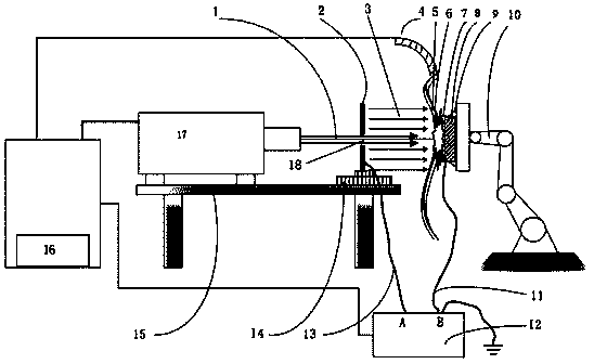
[0015] See attached figure 1 As shown, the laser shock peening device of the present invention with an externally strengthened electric field includes a high-power Q-switched laser shock peening power supply 16, a Q-switched high pulse energy laser 17, a high-voltage power supply 12, a 6-axis manipulator 10, a workbench 15, and a metal workpiece 8 to be strengthened. And the high-voltage electrode plate 2, the high-voltage end A of the high-voltage power supply 12 is connected to the electrode plate 2 through the wire II13, the electrode plate 2 is fixed on the workbench 15 through the first clamp 14 made of PTFE material, and the center of the electrode plate 2 is opened. Through the light hole 18 to ensure the passage of the laser light, a Q-switched high-pulse energy laser 17 is fixed on the workbench 15, and the automatic water spray device 4 sprays deionized water on the surface of the metal workpiece 8 to be strengthened as the constrained layer 5 of the laser shock treat...

Embodiment 2

[0028] See attached figure 1As shown, the laser shock peening device of the present invention with an externally strengthened electric field includes a high-power Q-switched laser shock peening power supply 16, a Q-switched high pulse energy laser 17, a high-voltage power supply 12, a 6-axis manipulator 10, a workbench 15, and a metal workpiece 8 to be strengthened. And the high-voltage electrode plate 2, the high-voltage end A of the high-voltage power supply 12 is connected to the electrode plate 2 through the wire II13, the electrode plate 2 is fixed on the workbench 15 through the first clamp 14 made of PTFE material, and the center of the electrode plate 2 is opened. Through the light hole 18 to ensure the passage of the laser light, a Q-switched high-pulse energy laser 17 is fixed on the workbench 15, and K9 optical glass with a thickness of 3 mm is used to cover the surface of the metal workpiece 8 to be strengthened in advance as the constraining layer 5 of the laser sh...


PUM


Abstract

The invention discloses a laser shock peening method for an outer intensified electric field. The method comprises the steps as follows: a laser shock peening device for the outer intensified electric field is provided, wherein the laser shock peening device for the outer intensified electric field comprises a high-powder Q-tuning laser shock peening power supply, a Q-tuning high-pulse energy laser device, a high-voltage power supply, a copper pole plate coupled to the high-voltage end A of the high-voltage power supply, an automatic spray device, a work bench and a six-axis manipulator; a DSP control system is internally built inside the high-powder Q-tuning laser shock peening power supply to achieve control of the intensified electric field and a laser shock peening time sequence; a light hole is formed in the center of the copper pole plate to ensure that the laser passes through the light hole; a work-piece is connected with the low-voltage end B of the high-voltage power supply through a high-voltage lead; the strong electric field of 100000-3000000V / m exists in the laser shock peening area; the laser is loaded before exiting, so as to affect the plasma excitation and constrained states of the laser shock peening process, and improve the laser shock peening efficiency and effect.

Description

technical field [0001] The invention relates to a laser shock strengthening method and device with an externally enhanced electric field, belonging to the field of intense pulse laser processing. Background technique [0002] In the field of metal material surface modification industry, laser shock strengthening technology is an advanced surface treatment technology that uses the mechanical effect generated by the plasma explosion shock wave induced by strong laser to improve the mechanical properties of materials. When the strong laser acts on the metal surface, electrons and positively charged metal ions will be excited. There are more peripheral electrons and more positively charged metal ions on the metal surface. [0003] The improvement effect of laser shock peening on the mechanical properties of metal materials is closely related to the effect area of ​​laser-induced plasma. Usually, when water or glass is used as the confinement layer, the energy of the pulsed lase...

Claims


Application Information

Patent Timeline
IPC IPC(8): C21D10/00
Inventor 邹世坤宋巍车志刚许海鹰曹子文
Owner BEIJING AERONAUTICAL MFG TECH RES INST
Learn More