

Gas flow control method for improving ionization efficiency of Hall thruster
A Hall thruster, gas flow technology, applied in thrust reversers, using plasma, machines/engines, etc., can solve the problems of low ionization efficiency and short neutral gas residence time, and achieve the effect of improving ionization efficiency
- Summary
- Abstract
- Description
- Claims
- Application Information
AI Technical Summary
Problems solved by technology
Method used
Image

Examples
specific Embodiment approach 1
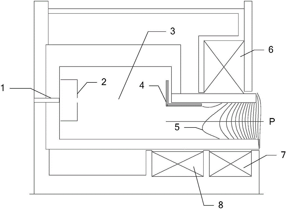
[0034] Specific implementation mode one: refer to Figure 2 to Figure 4 , Figure 17 to Figure 20 This embodiment is described in detail. The gas flow control method for improving the ionization efficiency of the Hall thruster described in this embodiment adopts a gas distributor, a gas outlet structure or a gas distributor and a gas outlet structure, and the gas distributor and the gas outlet structure are both It is a ring structure and can make the gas have a circumferential velocity component. The gas distributor and the gas outlet structure are fixed on the upstream part of the discharge channel. The axis of the gas distributor, the axis of the gas outlet structure and the axis of the discharge channel are all coincident. The gas distribution The device is located upstream of the upstream part, and the guide air outlet structure is located downstream of the upstream part.
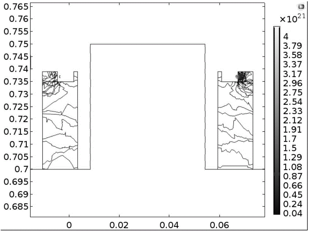
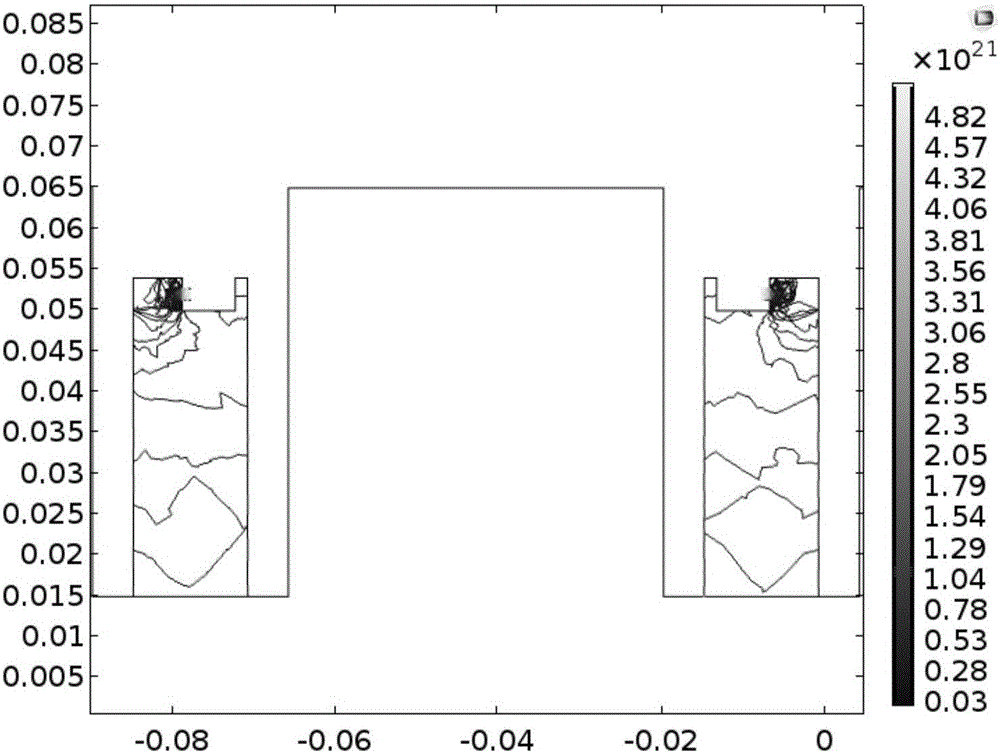
[0035] like Figure 2 to Figure 4 In order to use COMSOL software to simulate the distribution of...
specific Embodiment approach 2
[0037] Specific embodiment 2: This embodiment is a further description of the gas flow control method for improving the ionization efficiency of the Hall thruster described in the specific embodiment 1. In this embodiment, the gas distributor includes multiple groups of gas distribution chambers 9 and distribution chambers. The base 10 of the distributor, the base 10 of the distributor is a ring structure, and the multiple groups of gas distribution chambers 9 are evenly distributed in the circumferential direction of the distributor base 10, and each group of gas distribution chambers 9 includes at least one level of buffer and exhaust holes; The devices are distributed along the axial direction in turn;
[0038] Each stage of buffer includes at least one air inlet 9-1 and a buffer chamber 9-2;
[0039] The air intake hole and the buffer chamber are distributed along the axial direction in sequence, the air inlet hole 9-1 communicates with the buffer chamber 9-2, and the last...
specific Embodiment approach 3
[0042] Specific implementation mode three: refer to Figure 5 to Figure 9Describe this embodiment in detail. This embodiment is a further description of the gas flow control method for improving the ionization efficiency of the Hall thruster described in Embodiment 2. In this embodiment, the exhaust holes are arranged on the inner wall and outer wall of the buffer chamber Or on the inner wall and the outer wall, the exhaust holes of the multiple groups of gas distribution chambers 9 form at least one row of exhaust holes, and each row of exhaust holes is evenly distributed in the circumferential direction of the inner wall or the outer wall of the distributor base 10, and the rows on the inner wall The axes of the air hole and the exhaust hole on the outer wall are parallel to the transverse plane perpendicular to the axial direction of the gas distributor. The included angle between the axis and the radial direction of the gas distributor is a, the included angle between the ...
PUM
 Abstract
Description
Claims
Application Information