Inclination-angle-line-type fiber splicer capable of being opened and used repeatedly

An optical fiber splicer, tilt angle technology, applied in the coupling of optical waveguides, etc., can solve the problems of time-consuming and laborious, difficult splicing, splicing failure, etc., to reduce the cost of use, improve the quality of splicing, and simplify the degree of complexity.

Inactive Publication Date: 2012-01-11
JIANGSU UNIKIT OPTICAL TECH
View PDF7 Cites 0 Cited by
  • Summary
  • Abstract
  • Description
  • Claims
  • Application Information

AI Technical Summary

Problems solved by technology

[0003] When the front end is loaded into the V-groove assembly, the tail of the V-groove assembly is provided with a barb or ring groove for anti-loosening to press fit with the bayonet in the inner sleeve. Due to the high precision of the V-groove assembly, it cannot To withstand excessive pressing force, the depth of the barb or ring groove has to be reduced, and a spring needs to be pressed into the inner sleeve. The shallow groove must withstand the pushing force of the spring and also bear the pushing force during construction. The front thrust of the tube can easily push the V-groove assembly out, resulting in damage to the optical fiber and failure of the connection
[0004] When the rear end is installed into the V-groove assembly, the inner sleeve needs to be divided into two parts, the front sleeve and the spring seat, and the clamping form is used between them. There are two problems in this way. First, the clamping device is also pushed away by the spring force
Second, the cost of parts is higher than that of the front-mounted type
[0007] In the fixing of optical fiber, the thermal expansion and contraction of the metal sheet in the fixing mechanism will increase the distance of the optical fiber connection point, and the connection performance will change with temperature changes; while the plastic block is often closed to the optical fiber channel, the optical fiber When piercing, it is first necessary to push off the pressure block, but the smoothness of the plastic surface is low, and it is easy to damage the surface of the V-shaped groove during the push-off process, resulting in plastic debris, polluting the joint point, affecting light transmission, and resulting in a decline in the quality of the joint, while the joint plastic There is a liquid substance in the middle that improves the light transmittance. Its side effect is that the two surfaces are attracted together, and the pushing force of the optical fiber is greatly increased, resulting in difficulty in the final connection.
[0008] In the fixing of the outer skin, the process of installing the movable card seat, pushing the rotating shaft seat and rotating to the right angle together, and installing the dust cover is cumbersome, and the size of each part is small, time-consuming and labor-intensive. The small parts are difficult to manufacture and costly. Lost during construction; when pushed into the shaft seat, it cannot be fixed, but needs to be rotated into a right-angle position as a whole, which increases the difficulty and strength of construction and takes a long time to operate

Method used


Image

  • Inclination-angle-line-type fiber splicer capable of being opened and used repeatedly
  • Inclination-angle-line-type fiber splicer capable of being opened and used repeatedly
  • Inclination-angle-line-type fiber splicer capable of being opened and used repeatedly

Examples


Embodiment Construction

[0046] The present invention will be described in detail below in conjunction with the accompanying drawings.

[0047] Such as figure 1 , 2 , 3, 4, 5, 6, 7, 8, 9, 10, 11, 12, 13,

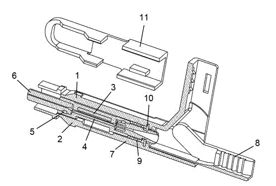
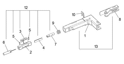
[0048] The adapter of the present invention includes a box assembly 12, a shell assembly 13, a spring 9, a card 10 and an opening cover 11, wherein the box assembly 12 includes a box body 2, a cover 3, a V-shaped groove metal block 4, and a latch 5. Ferrule 6 and guide block 7; a floating block 2-2 is arranged in the middle of the box body 2, and the two sides of the floating block 2-2 are respectively embedded groove 2-1 and building groove 2-5; the V-shaped The grooved metal block 4 is embedded in the embedded groove 2-5, and the opposite surface of the floating block 2-2 is provided with a V-shaped groove 4-1, and forms an optical fiber through hole 4-3 with it; the building cover 3 is attached to the box body 2 , the masonry 3-3 on one side of the cover 3 is pressed into the groove 2-5 of the...


PUM


Abstract

The invention discloses an inclination-angle-line-type fiber splicer capable of being opened and used repeatedly. The fiber splicer comprises: a cabinet assembly, a housing assembly, a spring, a card and an opening lid. The cabinet assembly comprises: a box, a brickwork cover, a V-shaped groove metal block, a bolt, a ferrule and a guide block. A floating block is arranged in a middle part of the box. An inserting slot and a brickwork slot are respectively on two sides of the floating block. The V-shaped groove metal block is inlaid in the inserting slot and a V-shaped groove is arranged on the V-shaped groove metal block. The V-shaped groove is arranged opposite to the floating block and a fiber through hole is formed between the V-shaped groove and the floating block. The brickwork cover is attached to the box. A brickwork body on one side of the brickwork cover is pressed into the brickwork slot of the box. A front connection chamber and a rear connection chamber are respectively arranged on two ends of the box. The front connection chamber is connected with the ferrule and the rear connection chamber is connected with the guide block. In the invention, a splice structure of the fiber splicer is compact. The fiber splicer is suitable for an indoor limited fiber panel box space, and is simple and reliable. On-site operation time is short. Difficulty of a fiber splicer terminal can be greatly reduced and total manufacturing costs are low.

Description

technical field [0001] The invention relates to a connection device for on-site installation of optical fibers. During the splicing process, a V-shaped groove assembly is installed from the front end of the splicing sub, and the optical fiber is compressed by box-building, and the outer skin is squeezed into the teeth of the elastic clamping seat. , by rotating the elastic card holder into the inclined card cavity of the inner sleeve to achieve oblique angle outlet, and can be opened and used repeatedly, specifically related to optical fiber splicers with two splicing methods of preset optical fibers or non-preset optical fibers. Background technique [0002] At present, the loading of the splice V-groove assembly is mainly divided into two types: front-end loading and rear-end loading, and there are also two ways to fix the optical fiber. [0003] When the front end is loaded into the V-groove assembly, the tail of the V-groove assembly is provided with a barb or ring groov...

Claims


Application Information

Patent Timeline
Patent Type & Authority Applications(China)
IPC IPC(8): G02B6/38
Inventor 吕根良黄金安
Owner JIANGSU UNIKIT OPTICAL TECH
Why Eureka
Try Eureka