Fixing structure of permanent magnet generator or motor permanent magnet

A permanent magnet generator and fixed structure technology, applied in the direction of magnetic circuit shape/style/structure, magnetic circuit rotating parts, etc., can solve the problems of large air gap, time-consuming and labor-intensive, permanent magnets are not firmly fixed, etc., to achieve magnetic field distribution Uniformity, reduced air gap, and improved efficiency

Inactive Publication Date: 2012-01-11
京能新能源科技(上海)有限公司
View PDF9 Cites 7 Cited by
  • Summary
  • Abstract
  • Description
  • Claims
  • Application Information

AI Technical Summary

Problems solved by technology

[0004] The purpose of the present invention is to solve the shortcomings of the existing permanent magnet generators that the permanent magnets are not firmly fixed and time-consuming and labor-intensive, and at the same time solve the problem of a large air gap in the existing method of bonding and fixing the permanent magnets, and provide a convenient and high-reliability, Permanent magnet fixed structure with high output power

Method used


Image

  • Fixing structure of permanent magnet generator or motor permanent magnet
  • Fixing structure of permanent magnet generator or motor permanent magnet
  • Fixing structure of permanent magnet generator or motor permanent magnet

Examples


Embodiment Construction

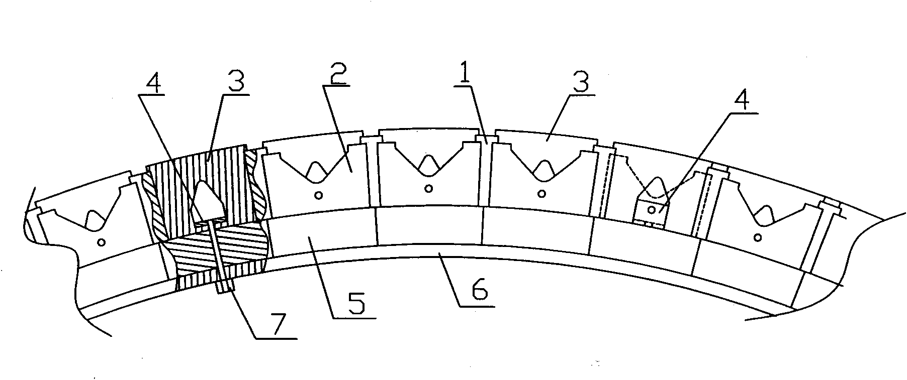
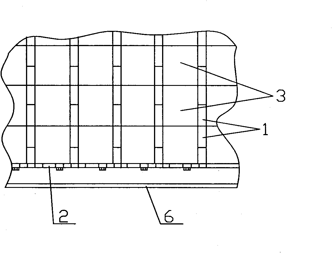
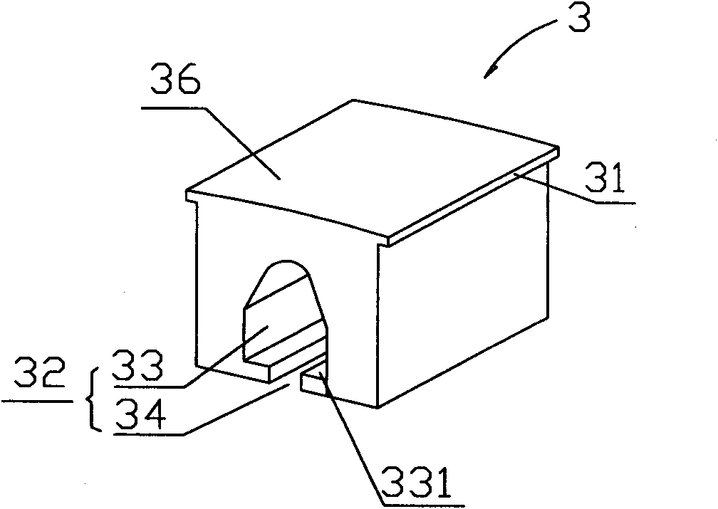
[0022] see figure 1 , 2 , the figure shows a permanent magnet generator or motor permanent magnet fixing structure according to the present invention, which includes a rotor cylinder 6, and several rows of permanent magnets 1 are arranged at uniform intervals along the surface circumference of the rotor cylinder 6; along the permanent magnets 1 is provided with a pole piece 3, and the two sides of the pole piece 3 are respectively provided with protrusions 31 for pressing the permanent magnets 1 on both sides; A channel for the permanent magnet 1 to penetrate is formed between two adjacent pole pieces, and the permanent magnet 1 is inserted into the channel and fixed on the two adjacent pole pieces 3 by the protrusions 31 on both sides thereof. Describe the surface of the rotor cylinder 6. Of course, the protruding portion 31 of the pole shoe 3 can be provided on the side of the pole shoe 3 , and at this time, only a groove is provided at a corresponding position on the side...


PUM


Abstract

The invention relates to a fixing structure of a permanent magnet generator or a motor permanent magnet. The fixing structure comprises a rotor cylinder and permanent magnets, wherein the permanent magnets are arranged along the circumference of the surface of the rotor cylinder at intervals. Pole shoes are arranged among the permanent magnets along the circumference of the surface of the rotor cylinder and are used for fixing the permanent magnets, and a protruding part for clamping tightly the permanent magnets on two sides is respectively arranged on two side surfaces of each pole shoe. Each permanent magnet is fixed on the surface of the rotor cylinder by virtue of adjacent pole shoes on the two sides of each permanent magnet. According to the invention, the problem that the fixation of a current generator permanent magnet is not firm and consumes time and labors is effectively solved, the air gaps between the rotor and the stator can be reduced and the working efficiency of the generator is improved.

Description

technical field [0001] The invention relates to a generator or a motor, in particular to a permanent magnet fixing structure of a permanent magnet generator or a motor. Background technique [0002] Permanent magnet generators are widely used in various power generation fields. In the existing permanent magnet generators, the permanent magnets are mostly fixed on the surface of the rotor cylinder structure (the permanent magnets are in the air gap). In order to fix the permanent magnets, glue is generally used to bond them to the surface of the rotor. Each permanent magnet must be pressed to the surface of the rotor until the bonding is firm. Large machines require hundreds of permanent magnets. The entire bonding and fixing process It is very time-consuming, and there is a problem of poor bonding. Although some brackets are used to help fix the permanent magnets, once there is a problem with the glue, the brackets cannot fix the permanent magnets, and the permanent magnets...

Claims


Application Information

Patent Timeline
Patent Type & Authority Applications(China)
IPC IPC(8): H02K1/28
Inventor 汉斯・鲁道夫・西格里斯特史人杰
Owner 京能新能源科技(上海)有限公司
Why Eureka
Try Eureka