Self-excitation push-pull type converter

A self-excited push-pull converter technology, applied in the field of DC-DC or DC-AC converters, can solve the problems of poor conversion efficiency and load capacity, poor start-up performance at low temperature, and decreased circuit conversion efficiency. To achieve the effect of making up for the large no-load operating current, good no-load operating current, and improved conversion efficiency

Active Publication Date: 2012-01-11
MORNSUN GUANGZHOU SCI & TECH
View PDF6 Cites 19 Cited by
  • Summary
  • Abstract
  • Description
  • Claims
  • Application Information

AI Technical Summary

Problems solved by technology

[0006] 1. Poor starting performance at low temperature
[0007] 2. The no-load power consumption is large at high temperature, and the conversion efficiency of the circuit decreases at high temperature
[0008] 3. The value of R1 in the starting circuit is not good enough to take into account the conversion efficiency and load capacity
In fact, the thermistor Rt2 reduces the conversion efficiency of the circuit, and also cannot solve the above-mentioned shortcoming of the prior art

Method used


Image

  • Self-excitation push-pull type converter
  • Self-excitation push-pull type converter
  • Self-excitation push-pull type converter

Examples


Embodiment Construction

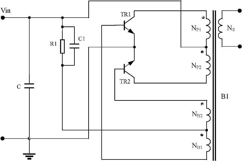
[0088] Figure 8 For the first embodiment, such as Figure 8 As shown, compared with the background technology figure 1 The difference is that the thermistor RT1 with a positive temperature coefficient is used to replace the original resistor R1, the main body of the circuit is a self-excited push-pull converter, and the secondary side of the transformer B1 is replaced by Image 6 In the circuit shown, the input DC is 5V, the output DC is 5V, the output current is 200n1A, that is, the output power is 1W.

[0089] Except for the thermistor RT1, the parameters of the circuit are completely the same as the circuit parameters corresponding to Table 1 to Table 4 in the background art. That is: capacitor C is a 1uF capacitor, capacitor C1 is a 0.1uF capacitor, triodes TR1 and TR2 are switching transistors FMMT491 with a magnification of about 200 times, and the maximum working current of the collector is 1A; the secondary output of the transformer adopts Image 6 The circuit stru...


PUM


Abstract

The invention discloses a self-excitation push-pull type converter comprising a starting circuit, wherein at least one biasing resistor in the starting circuit is a thermistor, and the starting circuit supplies base current larger than normal-temperature base current in value for the base of a push-pull type switch triode when being at low temperature; and the starting circuit can base current smaller than the normal-temperature base current in value for the base of the push-pull type switch triode when being at high temperature. The self-excitation push-pull type converter provided by the invention has favorable low-temperature starting performance, no-load power consumption at high temperature is not increased as comparison with no-load power consumption at low temperature, the converting efficiency of the circuit at high temperature is not reduced again and is maintained to be equal to or higher than the converting efficiency of the circuit at low temperature, and thus, the self-excitation push-pull type converter gives consideration to both converting efficiency and no-load power consumption within the whole working temperature range.

Description

technical field [0001] The invention relates to a DC-DC or DC-AC converter, in particular to a self-excited push-pull converter used in industrial control and lighting industries. Background technique [0002] The circuit structure of the existing self-excited push-pull converter comes from the self-excited oscillating push-pull transistor single-transformer DC converter invented by G.H.Royer in 1955, which is also the beginning of realizing high-frequency conversion control circuit; some circuits From the self-excited push-pull double-transformer circuit invented by Jen Sen in the United States in 1957, it was later called the self-oscillating Jensen circuit; these two circuits are collectively referred to as the self-excited push-pull circuit pull converter. The self-excited push-pull converter is described on pages 67 to 70 of "The Principle and Design of Switching Power Supply" published by Electronics Industry Press, and the book's ISBN number is 7-121-00211-6. The ma...

Claims


Application Information

Patent Timeline
Patent Type & Authority Applications(China)
IPC IPC(8): H02M3/337H02M1/36
CPCH02M1/36H02M3/3382
Inventor 刘伟王保均高晶郭国文
Owner MORNSUN GUANGZHOU SCI & TECH
Why Eureka
Try Eureka