High precision LED constant current drive unit

A constant-current drive, high-precision technology, applied in the field of LED lighting, can solve the problems of control errors, errors, and poor constant current effect, and achieve the effect of reducing system volume, simple circuit implementation, and good constant current effect.

Active Publication Date: 2012-01-11
QX MICRO DEVICES
View PDF5 Cites 10 Cited by
  • Summary
  • Abstract
  • Description
  • Claims
  • Application Information

AI Technical Summary

Problems solved by technology

In the actual circuit implementation, due to the delay of the hysteresis comparator, the actual peak value of the inductor current will exceed IL-H, assuming the excess value is Delta-ILH, and the actual valley value of the inductor current will be lower than IL-L, assuming the excess value is Delta -ILL, usually Delta-ILH and Delta-ILL are not equal, and the two change with the input voltage, output voltage, and operating frequency, resulting in a certain error between the actual average value of the inductor current and IL-AVE
Therefore, the constant current effect of the traditional hysteresis control LED drive circuit is not ideal.
[0003] In this way, the traditional hysteresis control LED drive circuit only controls the two points of the inductor current in one cycle, namely the peak value and the valley value, and due to the delay of the hysteresis comparator, there is always an error in the control of these two points, and this error It varies with input voltage, output voltage, and operating frequency, so the constant current effect is not good

Method used


Image

  • High precision LED constant current drive unit
  • High precision LED constant current drive unit
  • High precision LED constant current drive unit

Examples


Embodiment Construction

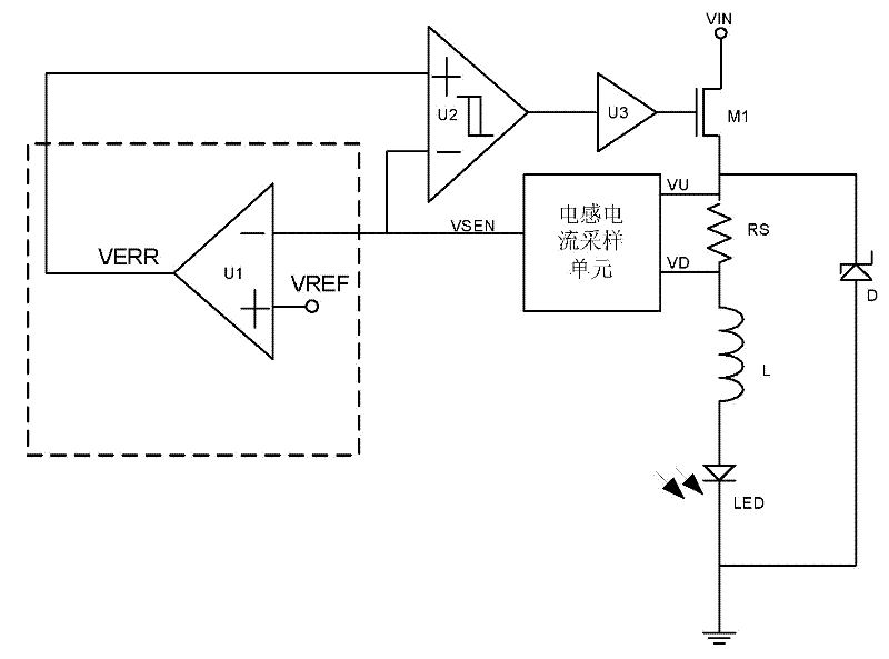
[0023] The first high-precision LED constant current drive device of the present invention, the circuit structure is as follows image 3 As shown, it includes an inductor L connected in series with the light-emitting LED lamp LED, a sampling resistor RS, and a first field effect transistor M1, and also includes a power drive module U3 and a hysteresis comparator U2 that are sequentially electrically connected to the gate of the first field effect transistor M1 , the first amplifier U1 and the inductor current sampling unit; the two input ends of the inductor current sampling unit are electrically connected to the two ends of the sampling resistor RS respectively, and the output end is electrically connected to the first input end of the first amplifier U1 and the hysteresis comparator The first input terminal of U2; the second input terminal of the hysteresis comparator U2 is electrically connected to the output terminal of the first amplifier U1; the second input terminal of t...


PUM


Abstract

The invention relates to a high precision LED constant current drive unit which comprises an inductor (L) which is in series connection with a luminescence LED lamp (LED), a sampling resistor (RS), and a first field effect transistor (M1). The high precision LED constant current drive unit also comprises a power driving module (U3), a retardation comparator (U2), a first amplifier (U1) and an inductance current sampling unit which are electrically connected with a grid of the first field effect transistor in order. Two input terminals of the inductance current sampling unit are electrically connected with two ends of the sampling resistor, and an output terminal of the inductance current sampling unit is electrically connected with a first input terminal of first amplifier and a first input terminal of the retardation comparator. A second input terminal of the retardation comparator is electrically connected with an output terminal of the first amplifier. A second input terminal of the first amplifier is electrically connected with a voltage references unit. The LED constant current drive unit has a good constant current effect, is insensitive to changes of input/output voltage, and can work with high frequency without sacrificing constant current precision. And a volume of an illumination system is reduced.

Description

technical field [0001] The invention relates to LED lighting, in particular to a high-precision LED constant current drive device. Background technique [0002] The LED constant current drive circuit based on hysteresis control has the advantages of simple control circuit structure, stability, and fast response, so it is widely used in high-power LED drive. Traditional hysteresis control LED constant current drive circuit, the circuit such as figure 1 As shown, it includes operational amplifier U11, hysteresis comparator U2 and power tube drive module U3. The circuit control principle is as figure 2 As shown, the inductor current is controlled within a hysteresis window. Ideally, the peak value of the inductor current is IL-H, the valley value of the inductor current is IL-L, and the average value of the inductor current is IL-AVE=(IL-H+ IL-L) / 2. In the actual circuit implementation, due to the delay of the hysteresis comparator, the actual peak value of the inductor cu...

Claims


Application Information

Patent Timeline
Patent Type & Authority Applications(China)
IPC IPC(8): H05B37/02
Inventor 李永红黄朝刚
Owner QX MICRO DEVICES
Why Eureka
Try Eureka