Wireless receiver and channel testing method thereof
A technology of a wireless receiver and a test method, applied in the field of communication, can solve the problems that multiple single channels cannot be tested in parallel, multiple channel combinations cannot be tested in parallel, and the test efficiency is low, so as to improve the channel test efficiency and solve the channel test. inefficient effect
- Summary
- Abstract
- Description
- Claims
- Application Information
AI Technical Summary
Problems solved by technology
Method used
Image
Examples
Embodiment 1
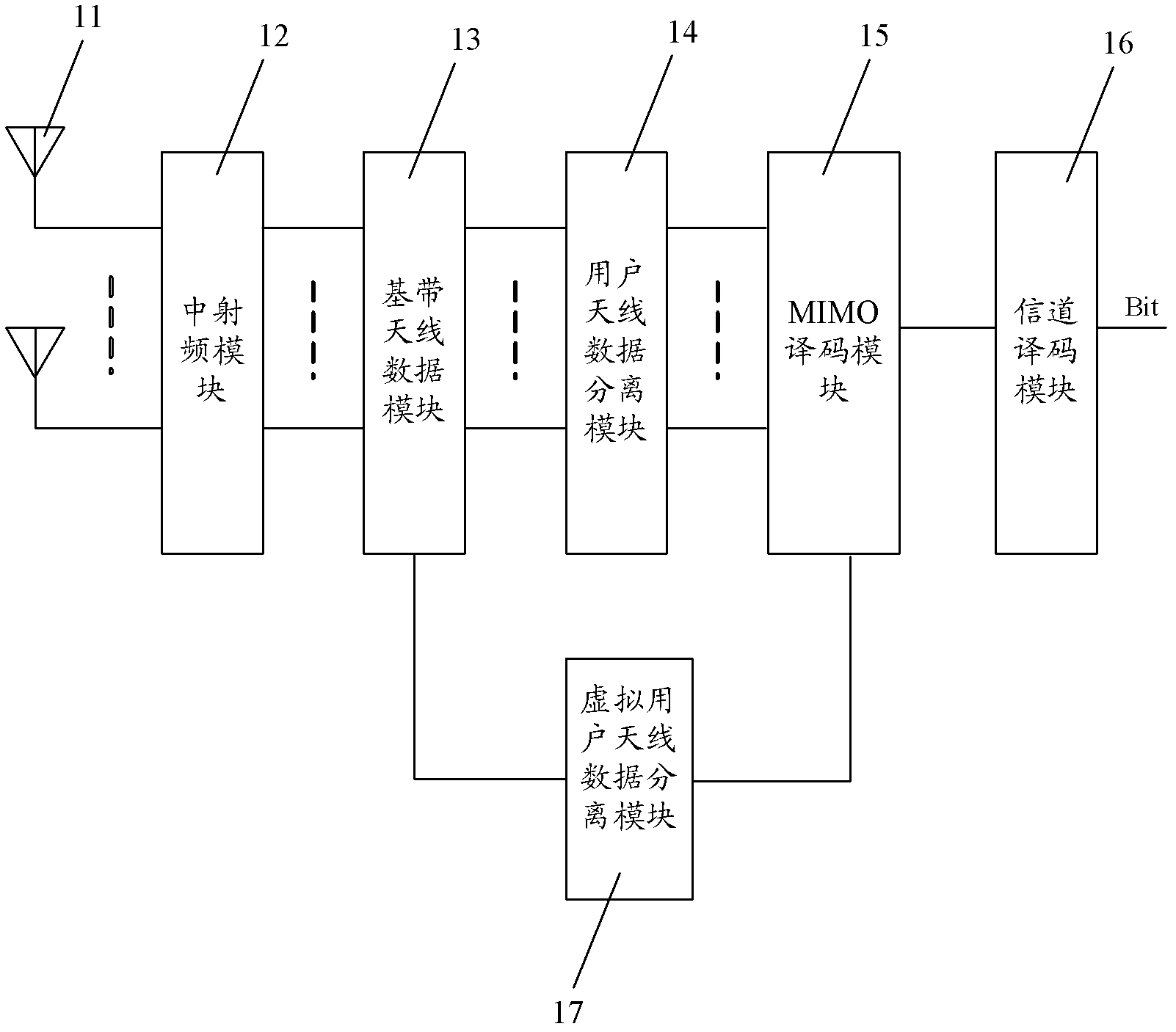
[0020] figure 1 It is a schematic structural diagram of a wireless receiver embodiment of the present invention, such as figure 1 As shown, the wireless receiver of this embodiment may include an antenna 11, an intermediate radio frequency module 12, a baseband antenna data module 13, a user antenna data separation module 14, and a Multiple Input Multiple Output (Multiple Input Multiple Output, referred to as: MIMO) decoding module 15. Channel decoding module 16 and virtual user antenna data separation module 17.
[0021] In the present embodiment, antenna 11 can receive test data, and this test data can be set as the data of a user when carrying out the channel test of wireless receiver; And, one antenna 11 corresponds to a channel, and the test data that it receives can enter The test data is transmitted in a corresponding channel, and the test data may be referred to as channel data. The middle radio frequency module 12 is connected to the antenna 11, and can perform filt...
Embodiment 2
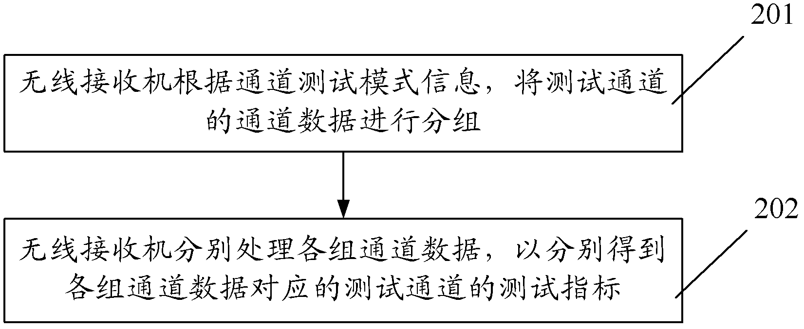
[0032] figure 2 It is a schematic flow chart of Embodiment 1 of the wireless receiver channel test method of the present invention. The wireless receiver channel test method of this embodiment can be executed by the wireless receiver described in any embodiment of the present invention. Such as figure 2 As shown, the method may include the following steps:
[0033] Step 201, the wireless receiver groups the channel data of the test channel according to the channel test mode information; the channel test mode information is single channel test or combined channel test;
[0034] For example, the single-channel test in the channel test mode information refers to the need to test the channel indicators (such as receiving sensitivity, demodulation threshold, etc.) of each channel separately; the joint channel test refers to the need to test the combined Channel index, to verify the signal reception performance of different channel combinations, wherein, the test of this joint c...
Embodiment 3
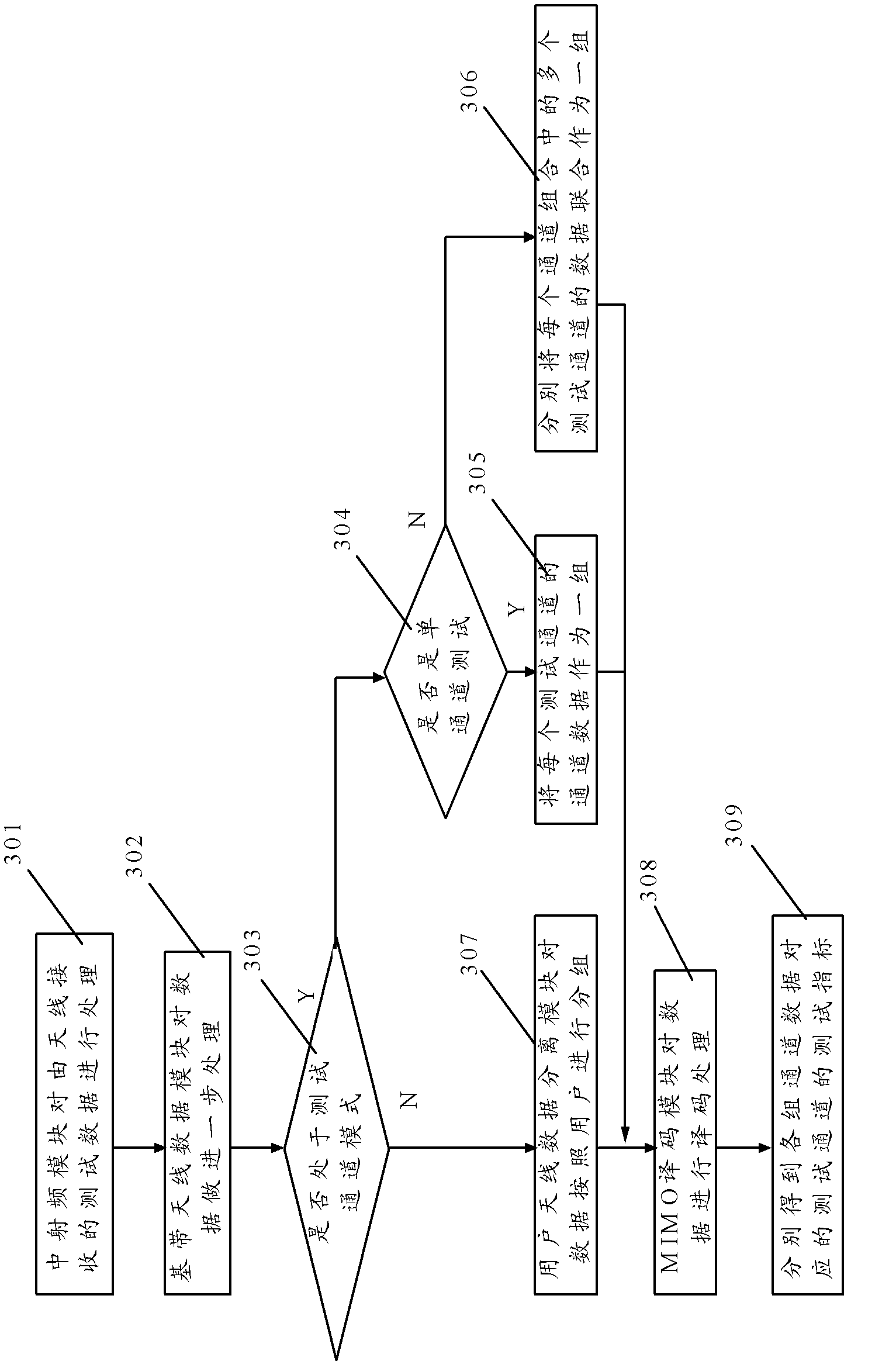
[0040] image 3 It is a schematic flow chart of Embodiment 2 of the wireless receiver channel test method of the present invention. The wireless receiver channel test method of this embodiment can be executed by the wireless receiver described in any embodiment of the present invention. Below to figure 1 wireless receiver shown as an example, combined with image 3 As shown, the method may include the following steps:
[0041] Step 301, the middle radio frequency module processes the test data received by the antenna;
[0042] For example, the mid-radio frequency module can filter and reduce the frequency of the test data, and convert the high-frequency test data received by the antenna into a time-domain signal.
[0043] Step 302, the baseband antenna data module further processes the data processed by the middle radio frequency module;
[0044] For example, the baseband antenna data module can further convert the test data into a baseband signal, at this time, it can be ...
PUM
 Abstract
Description
Claims
Application Information
 - R&D
- Intellectual Property
- Life Sciences
- Materials
- Tech Scout
- Unparalleled Data Quality
- Higher Quality Content
- 60% Fewer Hallucinations
Browse by: Latest US Patents, China's latest patents, Technical Efficacy Thesaurus, Application Domain, Technology Topic, Popular Technical Reports.
© 2025 PatSnap. All rights reserved.Legal|Privacy policy|Modern Slavery Act Transparency Statement|Sitemap|About US| Contact US: help@patsnap.com


