
A kind of testing method of dielectric loss and capacitance of cvt capacitor

A test method and capacitance technology, which is applied in the direction of capacitance measurement, electric variable measurement, resistance/reactance/impedance measurement, etc., can solve the problem of low test efficiency and achieve fast and accurate capacitance and dielectric loss values

Active Publication Date: 2020-07-17
YUNNAN POWER GRID CO LTD ELECTRIC POWER RES INST +1
View PDF11 Cites 0 Cited by
  • Summary
  • Abstract
  • Description
  • Claims
  • Application Information

AI Technical Summary

Problems solved by technology

[0005] This application provides a method for testing CVT capacitor dielectric loss and capacitance to solve the problem of low efficiency in traditional CVT capacitor dielectric loss and capacitance testing

Method used


Image

  • A kind of testing method of dielectric loss and capacitance of cvt capacitor
  • A kind of testing method of dielectric loss and capacitance of cvt capacitor

Examples


Embodiment Construction

[0018] The application will be described in detail below in conjunction with the accompanying drawings.

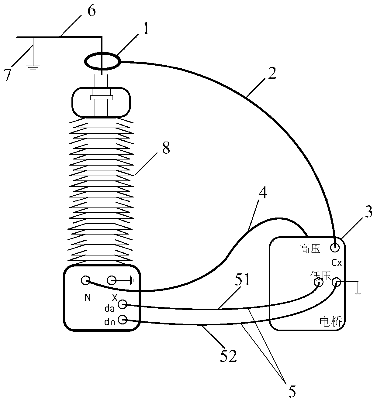
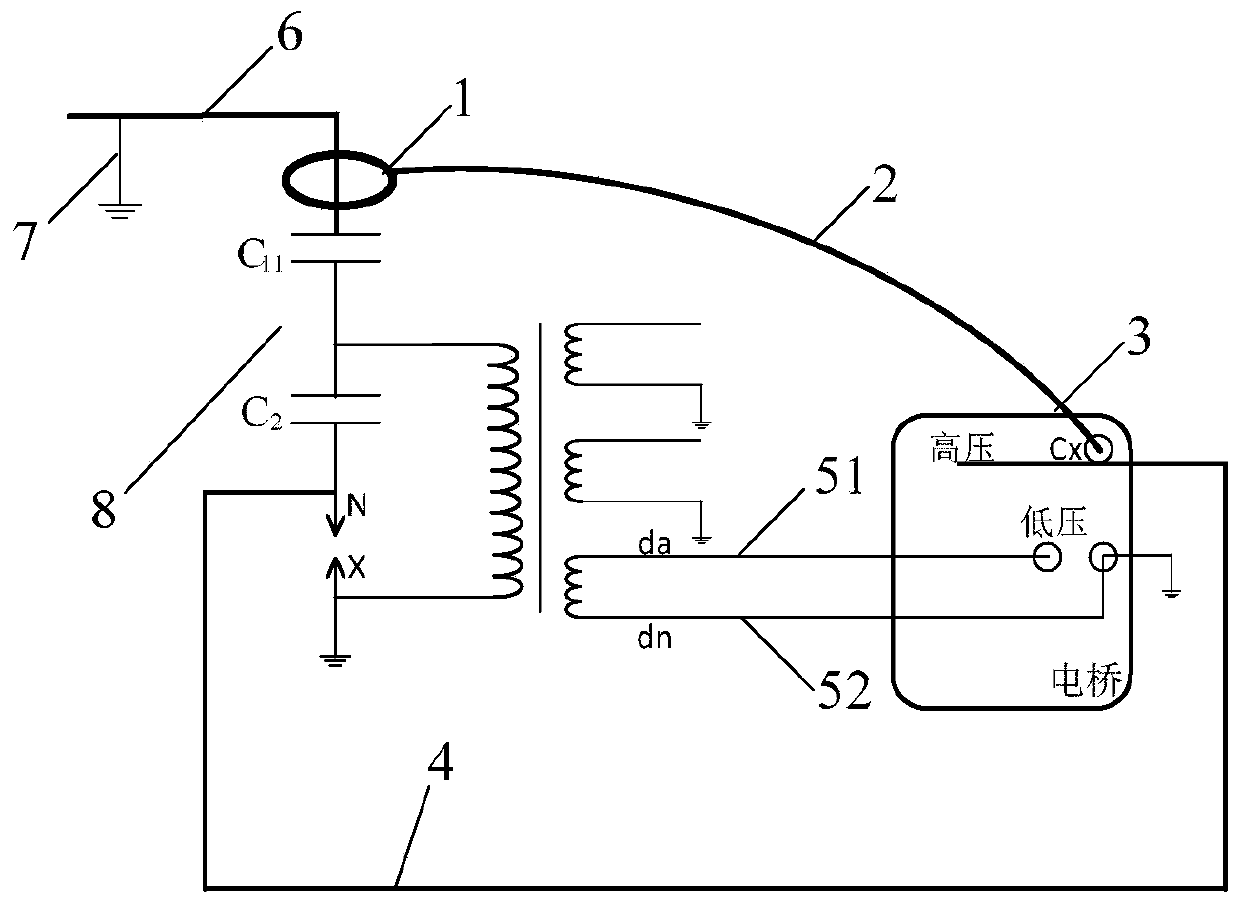
[0019] see figure 1 A schematic structural diagram of a test device for a CVT capacitor dielectric loss and capacitance provided by the application, as figure 1 As shown, the device includes: a differential current sensor 1 , a shielded test line 2 , a fully automatic anti-interference dielectric loss tester 3 , a high-voltage test test line 4 and a CVT self-excitation secondary pressure line 5 .

[0020] The differential current sensor 1 is clamped to the high-voltage drain end of the CVT8. The differential current sensor is a ring coil uniformly wound on a non-ferromagnetic material, and the output signal is the integral of the current to time. The circuit for integration can truly restore the input current. The high-voltage drain end of the CVT8 is connected to a high-voltage drain wire 6 , and the differential current sensor 1 is connected to the high-voltage drain w...


PUM


Abstract

An embodiment of the present application discloses a device and method for testing dielectric loss and capacitance of a CVT capacitor. A differential current sensor is clamped to a high voltage drainage end of the CVT, a band shielded test line is respectively connected to the differential current sensor and a full automatic anti-interference dielectric loss tester, a high voltage test line is connected to a high voltage test end of the full automatic anti-interference dielectric loss tester and a high voltage terminal of the CVT, a low voltage terminal of the CVT is grounded, a first CVT self-excited method secondary voltage step-up line is connected with a low-voltage test end of the full automatic anti-interference dielectric loss tester and a da terminal of the CVT, and a second CVT self-excited secondary pressurization line is connected to a ground connection end of the full automatic anti-interference dielectric loss tester and a dn end of the CVT. The differential current sensoris used to collect a current of a CVT main capacitor, and the full automatic anti-interference dielectric loss tester can be used for quickly and accurately testing capacitance and dielectric loss ofmain and secondary capacitors of the CVT.

Description

technical field [0001] The present application relates to the technical field of electrical measurement, in particular to a method for testing the dielectric loss and capacitance of a CVT capacitor. Background technique [0002] Capacitance type voltage transformer (CVT, Capacitance type voltage transformer) is used in the power system to measure voltage for meters and protection devices, and can also couple the carrier frequency to the transmission line for long-distance communication, remote measurement, and selective line high frequency protection etc. [0003] It is required in the preventive test procedure that when the electromagnetic unit is used as the power source to measure the capacitance and dielectric loss of the main capacitor and sub-capacitor of the capacitive voltage transformer capacitive voltage transformer, it should be carried out according to the manufacturer's regulations. The manufacturer adopts the CVT self-excited method for testing during the fact...

Claims


Application Information

Patent Timeline
Patent Type & Authority Patents(China)
IPC IPC(8): G01R27/26
CPCG01R27/2605
Inventor 朱启龙马宏明钱国超邹徳旭颜冰
Owner YUNNAN POWER GRID CO LTD ELECTRIC POWER RES INST
Learn More