
Cylindrical powder concentrator

A powder separator and cartridge technology, applied in the direction of solid separation, separation of solids from solids with airflow, chemical instruments and methods, etc., can solve the problems of complex system structure, low efficiency of powder selection, high energy consumption, etc., to achieve The effect of small size, reduced cost and low energy consumption

Active Publication Date: 2012-01-18
湖南广义节能装备有限公司
View PDF5 Cites 11 Cited by
  • Summary
  • Abstract
  • Description
  • Claims
  • Application Information

AI Technical Summary

Problems solved by technology

This kind of powder classifier can achieve the purpose of coarse particle powder selection, but because the airflow must be provided by an external fan, dust removal equipment must be installed to separate the fine powder from the gas, the powder selection efficiency is low, the energy consumption is high, and the system structure is complicated.

Method used


Image

  • Cylindrical powder concentrator
  • Cylindrical powder concentrator
  • Cylindrical powder concentrator

Examples


Embodiment 1

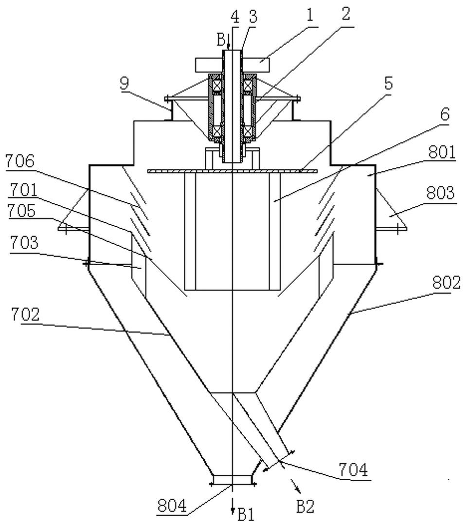
[0020] refer to figure 1 , this embodiment includes machine base 803, bearing seat 2, transmission wheel 1, hollow main shaft 3, material spreading disc 5, blade rotor 6, inner cylinder body, outer cylinder body, and the bearing seat 2 is installed on the machine cover 9 ; The hollow main shaft 3 is installed on the bearing housing 2 through bearings, and the feed port 4 is arranged above the hollow main shaft 3; A rotatable rotor part; the outer cylinder is composed of an upper outer cylinder 801 and a lower outer cylinder 802. The machine base 803 is arranged outside the outer cylinder for installation of the machine. Powder outlet 804; the inner cylinder is placed in the inner cavity formed by the outer cylinder. The inner cylinder is composed of an upper inner cylinder 701 and a lower inner cylinder 702. The upper inner cylinder 701 allows airflow to pass through the upper part to classify the material The functional cylindrical classifying device 706 (single-cylinder str...

Embodiment 2

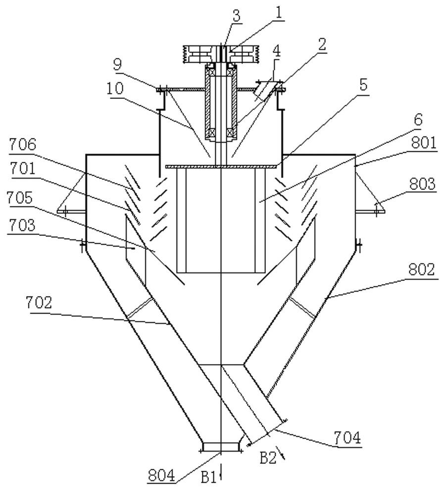
[0024] refer to figure 2 Compared with Embodiment 1, the main difference between this embodiment and Embodiment 1 is that the main shaft 3 is a solid shaft, and the feed port 4 is located outside the bearing seat 2, so that the material slips from the feed pipe 10 into the spreader 5; the cylindrical classification device 706 It is composed of two layers inside and outside.

Embodiment 3

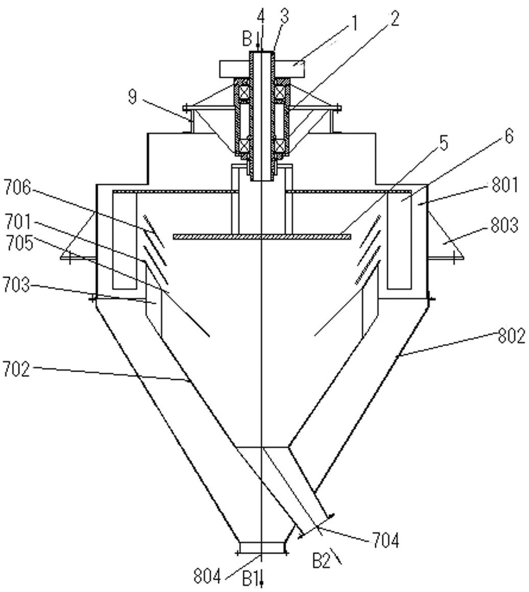
[0026] refer to image 3 In this embodiment, the blade rotor 6 of Embodiment 1 is assembled on the hollow main shaft 3 through a connecting piece, located inside the upper outer cylinder 801 and outside the upper inner cylinder 701, the wind generated by the rotation of the blade rotor 6, Compared with the cylindrical grading device 706, it is sucked from the inside to the outside. Its working principle is identical with embodiment 1.


PUM


Abstract

The invention discloses a cylindrical powder concentrator, which comprises a machine seat, a bearing seat, a transmission wheel, a main shaft, a scattering plate, a fan-blade rotor, an inner cylinder, an outer cylinder and a feeding hole, wherein the main shaft is arranged on the bearing seat through a bearing; the transmission wheel, the scattering plate and the fan-blade rotor are assembled on the main shaft; the outer cylinder consists of an upper outer cylinder and a lower outer cylinder; the lower part of the lower outer cylinder is provided with a fine powder outlet; the inner cylinder is arranged in a cavity formed by the outer cylinder; the inner cylinder consists of an upper inner cylinder and a lower inner cylinder; the lower part of the lower inner cylinder is provided with a coarse powder outlet; an return air blade is arranged between the upper inner cylinder and the lower inner cylinder; the fan-blade rotor is arranged on the inner side of the upper inner cylinder or between the inner side of the upper outer cylinder and the outer side of the upper inner cylinder; or fan-blade rotors are arranged on the inner side of the upper inner cylinder as well as between the inner side of the upper outer cylinder and the outer side of the upper inner cylinder; and the upper inner cylinder consists of an upper cylindrical grading device and a lower coarse powder passing cone. The cylindrical powder concentrator has a simple structure, high efficiency and low energy consumption, and is mainly applied to powder concentration and grading of coarse particles or materials with large specific weights.

Description

technical field [0001] The invention relates to a dry separation device for powdery materials, in particular to a dry separation device for large specific gravity materials or coarse-grained powdery materials used in metal ore, non-metallic ore, new materials and other industries. Background technique [0002] Most of the existing dry powder separators are dynamic powder separators, including centrifugal, cyclone, rotor and other types. A common feature of these types of powder separators is that they use wind to blow materials from bottom to top, and the materials are blown When it reaches the grading rotor or small fan blades that act as a fence, the coarser materials will fall into the coarse powder area due to the gravity, centrifugal force, etc., so that the downward force is greater than the upward force, and the fine powder will continue to go up and enter the fine powder area. area, thereby realizing the grading of powder. However, the above-mentioned equipment is n...

Claims


Application Information

Patent Timeline
IPC IPC(8): B07B7/083
Inventor 夏纪勇王大臣
Owner 湖南广义节能装备有限公司
Learn More