Manufacture die for carbon fiber composite integrative multipass joint and preparation method thereof

A technology of composite materials and multi-way joints, applied in the field of composite material space trusses, can solve the problems of artificial weaving, heavy weight of metal connectors, low efficiency, etc., and achieve the effect of improving bearing capacity, reducing stress concentration, and good quality of finished products

Inactive Publication Date: 2012-01-18
BEIHANG UNIV
View PDF4 Cites 19 Cited by
  • Summary
  • Abstract
  • Description
  • Claims
  • Application Information

AI Technical Summary

Problems solved by technology

[0002] For the recent research hotspot of stratospheric aerostats, the connection of its large lightweight carbon fiber composite truss structure has become a bottleneck technology. Generally, the weight of metal connectors is large, and the connection between metal joints and carbon fiber rods is discrete. Electrocorrosion between metal joints affects the service life of the structure and other problems. It is necessary to study a lightweight and

Method used


Image

  • Manufacture die for carbon fiber composite integrative multipass joint and preparation method thereof
  • Manufacture die for carbon fiber composite integrative multipass joint and preparation method thereof
  • Manufacture die for carbon fiber composite integrative multipass joint and preparation method thereof

Examples


preparation example Construction

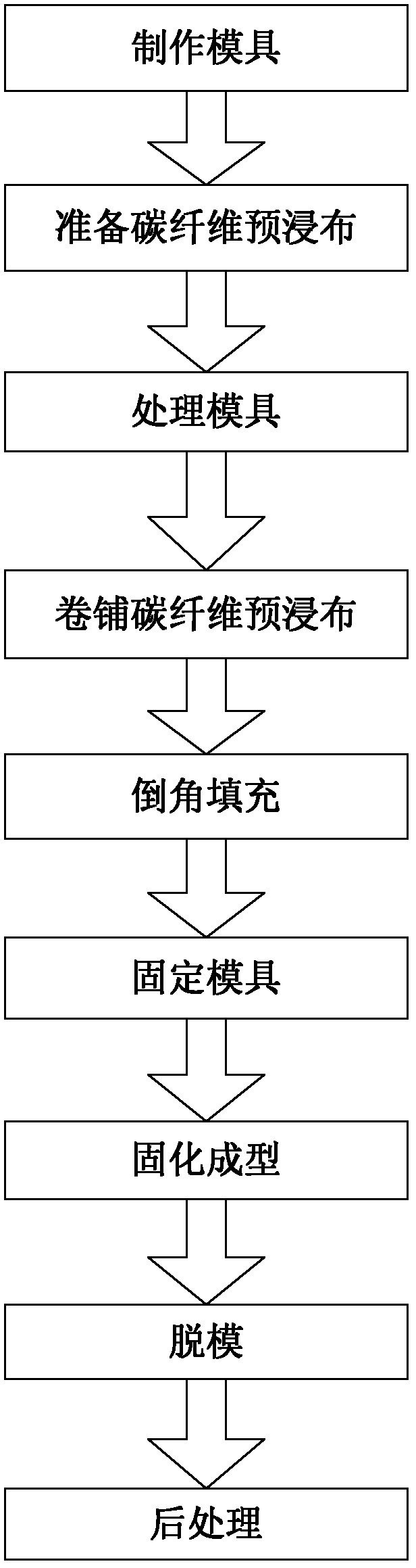
[0042] The preparation method of the carbon fiber composite material integrated multi-way joint of the present invention, such as figure 1 shown, including the following steps:

[0043] Step 1: Make a mold according to the design requirements of the carbon fiber composite integrated multi-way joint, and the mold includes a female mold and a male mold;

[0044] The male mold is made of silica gel, and the female mold is made of steel. The coefficient of thermal expansion of silica gel is greater than that of the material steel of the female mold. Therefore, the use of silica gel can increase the pressure of the mold on the carbon fiber product during the production process and improve the quality of the product.

[0045] At the sudden change in the section of the carbon fiber composite joint, make chamfers to reduce the local stress, but because the thickness of the carbon fiber cloth at the chamfers changes greatly, the chamfers need to be filled with carbon fiber filaments to...

Embodiment

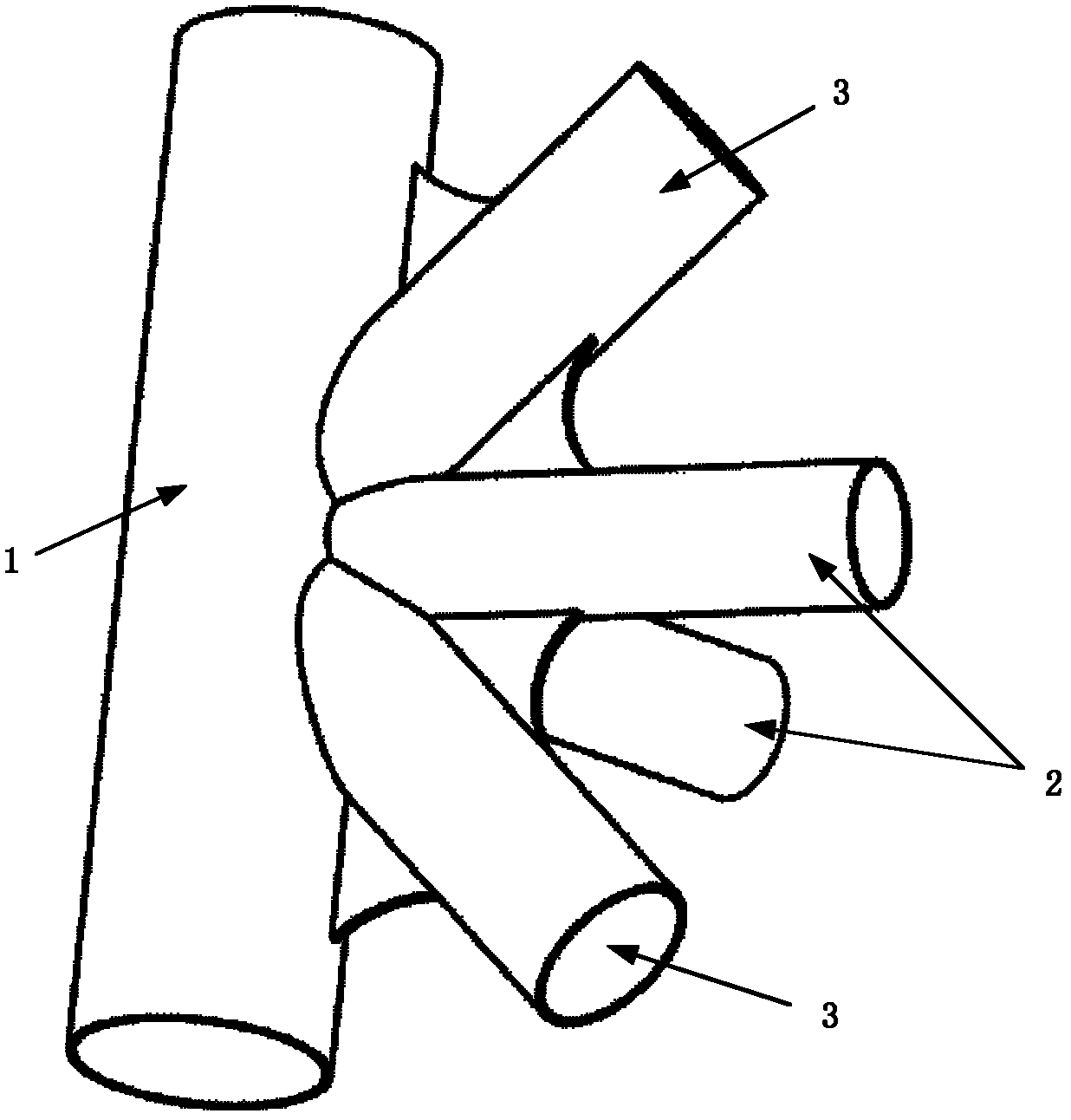
[0056] The carbon fiber composite material integrated joint in this embodiment, such as figure 2 As shown, it includes one main sleeve 1, two oblique sleeves 2 and two straight sleeves 3, the angle between the main sleeve 1 and the oblique sleeve 2 is 45°, the main sleeve 1 and the straight sleeve The angle between 3 is 90°.

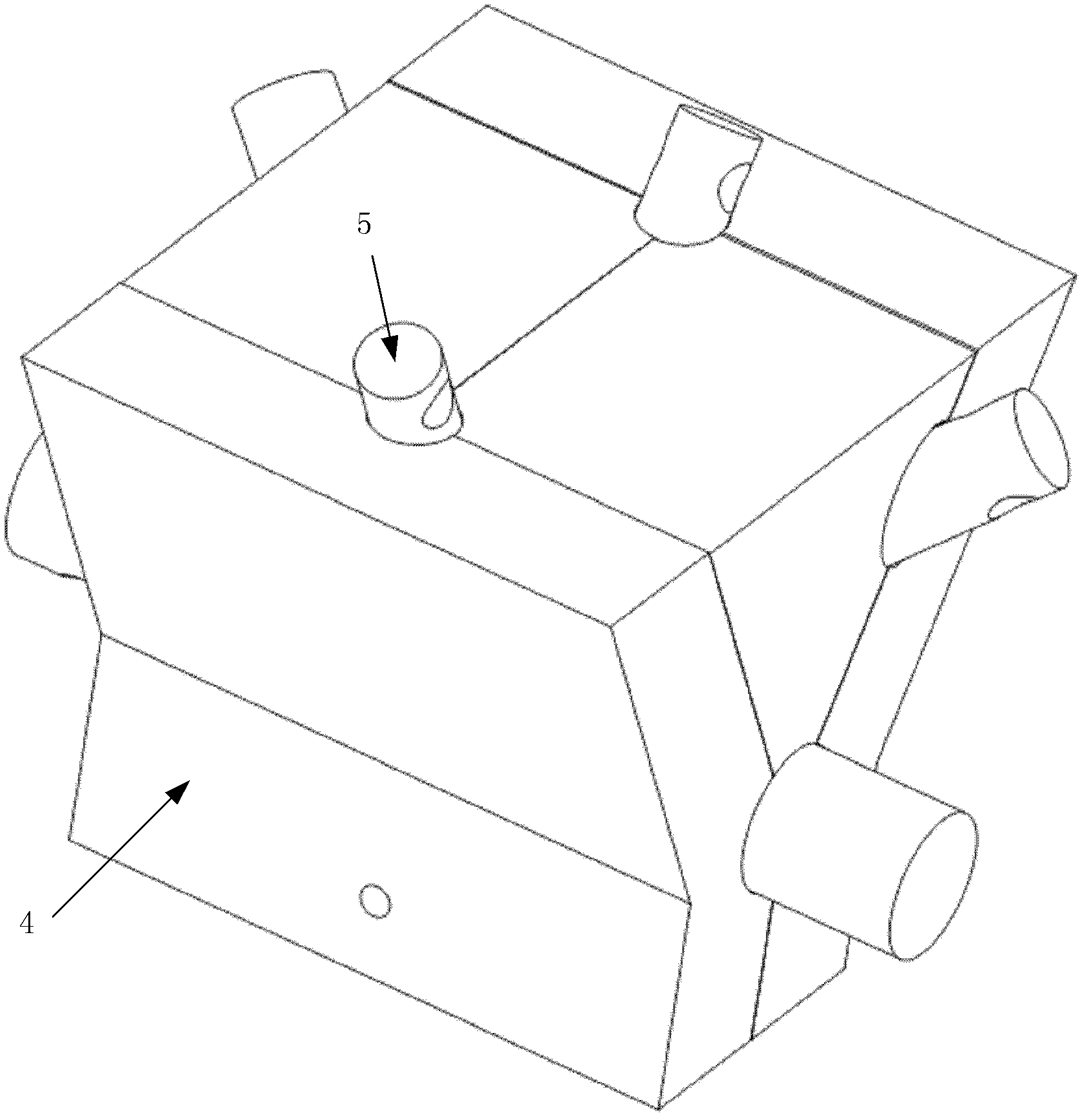
[0057]The production mold of the integrated joint of carbon fiber composite material is as follows: image 3 As shown, including the female mold 4 and the male mold 5, the female mold 4 as a whole is as Figure 4 As shown, it is made of steel and consists of 4 parts, including upper female mold 401, lower female mold 402, left female mold 403 and right female mold 404, as Figure 5 shown. The whole male mold 5 is as Figure 6 As shown, the male mold 5 is made up of 5 silicone parts, including the main rod male mold 501, two oblique rod male molds 502 and two bulkhead rod male molds 503, as Figure 7 shown. The mold is fastened by bolts.

[0058] ...


PUM


Abstract

The invention discloses a manufacture die for a carbon fiber composite integrative multipass joint and a preparation method thereof. The manufacture die for a carbon fiber composite integrative multipass joint is manufactured according to the specific requirement of the integrative multipass joint and comprises a male die and a female die, wherein the male die is made of silica gel, and the female die is made of steel; and a section mutation of the integrative multipass joint is provided with a chamfer in which carbon fiber filaments are filled. In the manufacture die, a silica gel male die and a steel male die are combined, pressure on the carbon fiber composite material by the die is effectively improved, and the quality of the carbon fiber composite workpiece is improved. In addition, the manufacture die adopts the chamber filling technology, the stress concentration phenomenon on the shape mutation position of the joint is reduced, and the bearing capability of the joint is effectively improved.

Description

technical field [0001] The invention provides a manufacturing mold and a preparation method of a carbon fiber composite material integrated multi-way joint, belonging to the technical field of composite material space trusses. Background technique [0002] For the recent research hotspot of stratospheric aerostats, the connection of its large lightweight carbon fiber composite truss structure has become a bottleneck technology. Generally, the weight of metal connectors is large, and the connection between metal joints and carbon fiber rods is discrete. Electrocorrosion between metal joints affects the service life of the structure and other problems. It is necessary to study a lightweight and efficient carbon fiber composite material connector to solve the above problems. [0003] The existing carbon fiber composite material connectors generally use the three-dimensional braided RTM process, but due to the complex shape of the integrated joints, the current three-dimensional...

Claims


Application Information

Patent Timeline
IPC IPC(8): B29C70/54B29C70/30
Inventor 陶国权马云鹏傅磊黄雨霓董阿鹏
Owner BEIHANG UNIV
Why Eureka
Try Eureka