Distribution conveyor

A cloth conveying and conveyor belt technology, which is applied in the field of cloth conveyors, can solve the problems of restrained conveying efficiency, inconvenient operation, complicated operation, etc., and achieve the effects of improved site utilization, stable equipment operation, and simple structure

Inactive Publication Date: 2012-01-18
安徽君鹏机械有限公司
View PDF5 Cites 6 Cited by
  • Summary
  • Abstract
  • Description
  • Claims
  • Application Information

AI Technical Summary

Problems solved by technology

The conveying line of the existing cloth conveyor is usually fixed, such as the horizontal conveying mechanism of ordinary linear conveying, which can only convey the tape arranged along the horizontal straight line from the starting point to the end point, and the dropping point is fixed. After the material is piled up at the end point, it is necessary to move the entire horizontal conveying mechanism to change its material stacking point, which is inconvenient to operate and its site utilization rate is low, and the conveying efficiency is greatly suppressed. The conveying direction is provided with a vertical conveying mechanism. The vertical conveying mechanism can reciprocate along the conveying direction of the horizontal conveying mechanism. After the material is fed from the feed end of the horizontal conveying mechanism, it is conveyed along its conveyor belt to the conveyor belt of the vertical conveying mechanism, and finally by the vertical conveying mechanism. The conveyor belt of the conveying mechanism transports the material to the blanking point, so as to realize the controllable blanking of the blanking point. The above method still has the following defects: First, because the vertical conveying mechanism is always parallel to the direction of movement of the horizontal conveying mechanism, resulting in the The passing path is also always parallel to the horizontal conveying mechanism, which eventually leads to the "relatively" fixed feeding point, and the low utilization rate of the stacking site still exists; secondly, due to the additional mechanism, the overall volume is larger When the path is full of materials and the entire device needs to be moved, the operation becomes more complicated and the overall handling is inconvenient

Method used


Image

  • Distribution conveyor
  • Distribution conveyor
  • Distribution conveyor

Examples


Embodiment Construction

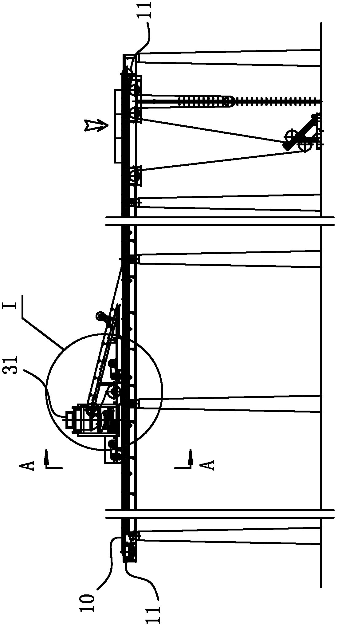
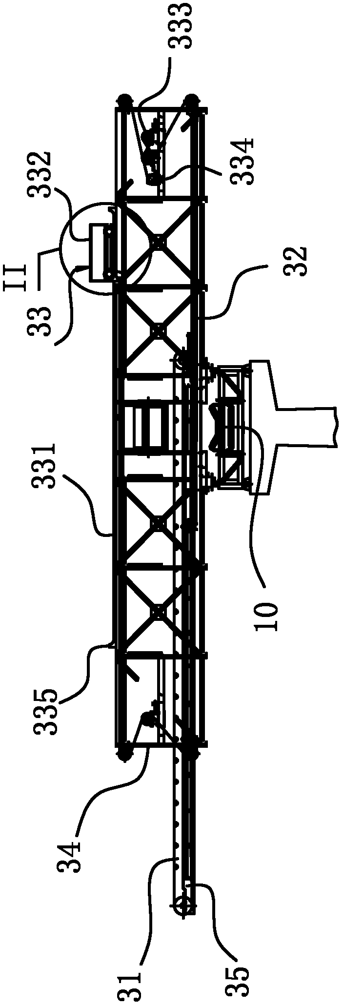
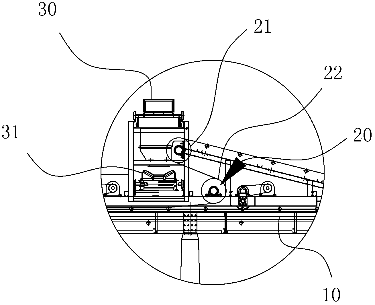
[0010] A cloth conveyor, comprising a first conveyor belt 10, the belt body between the guide rollers 11 at both ends constituting the first conveyor belt 10 is provided with a steering wheel that can make the belt body turn back obliquely upwards in a suspended state Roller 20, said first conveyor belt 10 is also erected with a driving device 30 that can reciprocate along the first conveyor belt 10, said driving device 30 is provided with an extension mechanism 31, and said extension mechanism 31 is for conveying Belt, the blanking point of the suspended belt body of the first conveyor belt 10 is always located above the belt body of the extension mechanism 31, such as Figure 1-3 shown.

[0011] Further, the turning rollers 20 are two and arranged in parallel, and the turning rollers 20 and the driving device 30 follow up, so as to realize the follow-up between the blanking point of the first conveyor belt 10 and the belt body of the extension mechanism 31 , so that the bla...


PUM


Abstract

The invention belongs to the field of a conveyor, and particularly relates to a distribution conveyor. The distribution conveyor comprises a first conveyer belt, wherein a steering roller which enables a belt body to fold back diagonally upwards in a suspension manner is arranged on the belt body between guide rollers at two end parts of the first conveyer belt; a driving device which can reciprocate along the first conveyer belt is erected on the first conveyer belt; an extension mechanism is arranged on the driving device; the extension mechanism is a conveyer belt; and a blanking point of the suspended belt body of the first conveyer belt is always located above a belt body of the extension mechanism. The whole field distribution can be realized, the structure is simple, the device works stably, and compared with the traditional conveyor, the field utilization ratio of the distribution conveyor is greatly improved.

Description

technical field [0001] The invention belongs to the field of conveyors, in particular to a cloth conveyor. Background technique [0002] A conveyor is a material handling machine that continuously conveys materials on a certain route, also known as a continuous conveyor. The conveyor can carry out horizontal and inclined conveying, and can also form a space conveying line. The conveying line of the existing cloth conveyor is usually fixed, such as the horizontal conveying mechanism of ordinary linear conveying, which can only convey the tape arranged along the horizontal straight line from the starting point to the end point, and the dropping point is fixed. After the material is piled up at the end point, it is necessary to move the entire horizontal conveying mechanism to change its material stacking point, which is inconvenient to operate and its site utilization rate is low, and the conveying efficiency is greatly suppressed. The conveying direction is provided with a ...

Claims


Application Information

Patent Timeline
Patent Type & Authority Applications(China)
IPC IPC(8): B65G47/46
Inventor 徐尚鹏
Owner 安徽君鹏机械有限公司
Why Eureka
Try Eureka