
Mold for preparing glass container

A technology of glass containers and molds, which is applied in the direction of glass blowing molds, etc., can solve the problems of easy blockage of air vents, complex overall structure of valves, lack of consistency of wall thickness at the neck and shoulders, etc., and achieve the effect of not being easy to block

Inactive Publication Date: 2012-01-18
CHANGSHU JIANHUA MOLD TECH
View PDF10 Cites 17 Cited by
  • Summary
  • Abstract
  • Description
  • Claims
  • Application Information

AI Technical Summary

Problems solved by technology

However, this patent application scheme has been proved by practice to still have shortcomings: one, it is not enough to guarantee the overall plumping effect of the neck and shoulders, and it is easy to appear that one is thicker and the other is thinner or one is thinner and the other is thicker, that is to say, the wall thickness of the neck and shoulders is different. Lack of consistency; second, the overall structure of the valve is very complex and difficult to process, especially the coordination of the valve hole is difficult, for example, the first air discharge channel formed between the valve head and the hole wall of the valve hole is often difficult to control; The third is that the exhaust gap is easy to block, the cleaning frequency is high, and the cleaning is difficult. If it is not cleaned in time, the exhaust function will disappear. Cavity, that is, the mold cavity is added with a release agent, and the release agent and glass dust during the molding process of the product are easy to block the exhaust gap.

Method used


Image

  • Mold for preparing glass container
  • Mold for preparing glass container
  • Mold for preparing glass container

Examples


Embodiment Construction

[0021] In order to enable the examiners of the patent office, especially the public, to understand the technical essence and beneficial effects of the present invention more clearly, the applicant will describe in detail the following in the form of examples, but none of the descriptions to the examples is an explanation of the solutions of the present invention. Any equivalent transformation made according to the concept of the present invention which is merely formal but not substantive shall be regarded as the scope of the technical solution of the present invention.

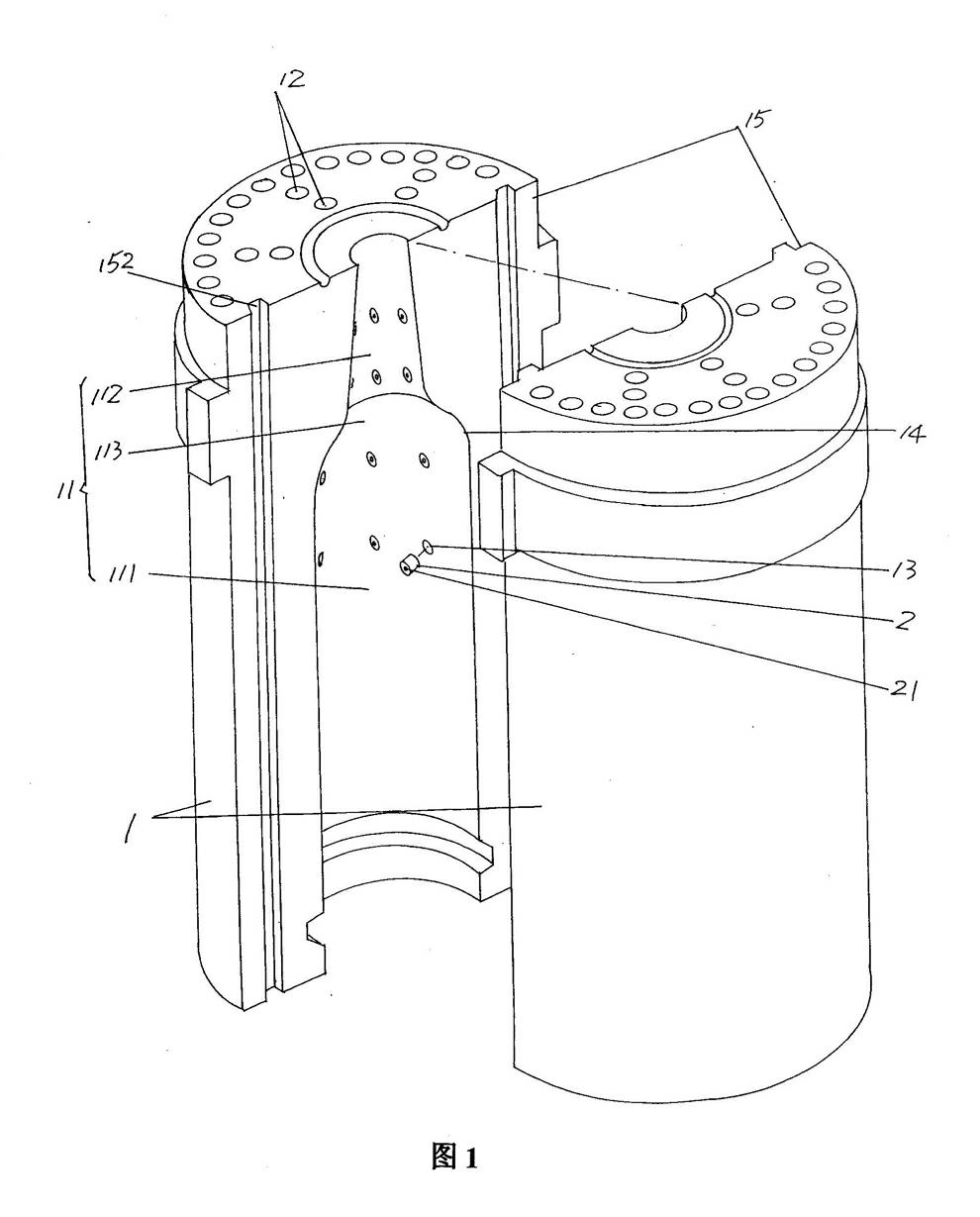
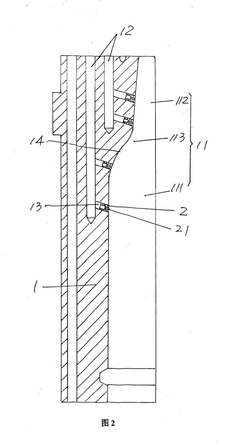
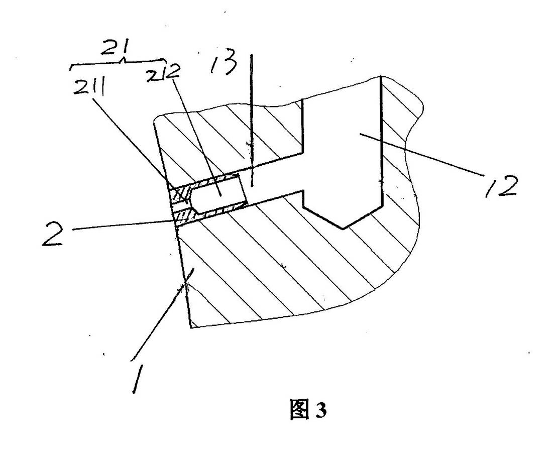
[0022] Please see figure 1 and figure 2 ,exist figure 1 A pair of bottle half-molds 1 that are opposite to each other, that is, arranged face to face, are provided in the present invention. The bottle half-molds 1 of this structural form can be used to make red wine bottles. Each bottle half-mold 1 has a bottle half-mold cavity 11 and has a surrounding The semicircular direction of the bottle half-...


PUM


Abstract

The invention relates to a mold for preparing a glass container, and belongs to the technical field of glass mold. The mold comprises a pair of bottle half-molds, wherein the bottle half-molds are arranged relatively. Each bottle half-mold is provided with a bottle half-mold cavity and axial vent holes, wherein the axial vent holes are axially parallel to the bottle half-mold cavity, and are communicated with the outside environment. The mold is characterized in that: each bottle half-mold is further provided with radial vent holes adopted as channels, wherein the bottle half-mold cavity and the axial vent holes are communicated through the channels. The radial vent holes are arranged around neck regions and shoulder regions of the bottle half-molds, and have plural columns, wherein the plural columns are arranged separatedly. Each column has plural radial vent holes, wherein the plural radial vent holes are arranged separatedly. A valve core is fixedly arranged on a hole opening position of each radial vent hole, wherein the center of the valve core is provided with a core hole, the hole opening position of the radial vent hole is toward the bottle half-mold cavity. The mold has the following advantages that: the uniformity effects of the wall thicknesses of the neck region and the shoulder region can be ensured; the overall structure is simple, the mold is easy to manufacture and install; the valve core is not easily be blocked.

Description

technical field [0001] The invention belongs to the technical field of glass moulds, in particular to a mold for making glass containers. Background technique [0002] The molds defined above by the applicant for making glass containers refer specifically to molds for processing glass containers with necks and shoulders, such as beer bottles, various condiment bottles, red wine bottles and soda bottles, etc. wait. In the process of processing glass containers with neck and shoulders from bottle glass molds, the deformation of the neck and shoulders of the glass containers is the most difficult problem for the industry. Although people have already formed a consensus on the causes of neck and shoulder deformation, but so far there is no good way to deal with it. The reason for the deformation of the neck part is that during the final blowing (when the glass prototype is blown into a finished glass bottle), the speed is relatively fast, and the gas inside the cavity cannot b...

Claims


Application Information

Patent Timeline
IPC IPC(8): C03B9/34
Inventor 马建华朱伟国晏庆宝
Owner CHANGSHU JIANHUA MOLD TECH
Learn More