
Horizontal stirring methane fermentation device with vertical cylindrical tank

A biogas fermentation and cylinder technology, applied in biochemical cleaning devices, enzymology/microbiology devices, bioreactor/fermenter combinations, etc., can solve the problem of not exceeding 500 cubic meters, not too high concentration, high construction cost, etc. problems, to achieve the effect of strong overwintering ability, high feed concentration, low operating cost and construction cost

Active Publication Date: 2013-07-17
朱林
View PDF6 Cites 0 Cited by
  • Summary
  • Abstract
  • Description
  • Claims
  • Application Information

AI Technical Summary

Problems solved by technology

[0002] At present, the commonly used high-efficiency biogas fermentation devices are CSTR, UASB, USR, and HCPF. CSTR is a cylindrical vertical upflow high-concentration biogas fermentation process, and the cost is relatively cheap, but the concentration of this process should not be too high, because It relies on the sewage pump to feed the material, and there is no big agitator, which limits the increase of its concentration, and the highest can only reach 8%. UASB and USR two processes are also cylindrical vertical, although the cost is cheap but the concentration is lower. , so that these three kinds of operating costs are relatively high; HCPF is a horizontal mixer plug-flow high-concentration anaerobic fermentation process, its concentration is relatively high up to 12%, and its operating cost is relatively low, but because it is horizontal , it is determined that it cannot be built large, and it cannot exceed 500 cubic meters at most, so its construction cost is particularly high

Method used


Image

  • Horizontal stirring methane fermentation device with vertical cylindrical tank
  • Horizontal stirring methane fermentation device with vertical cylindrical tank

Examples


Embodiment Construction

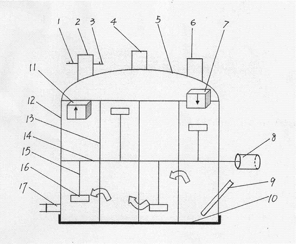
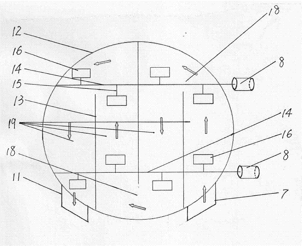
[0013] as attached figure 1 , 2 As shown, the biogas fermentation device is a cylindrical vertical fermentation tank with a diameter of 16 meters. Three partitions 13 are longitudinally arranged in the tank body 12. The partitions 13 are parallel to each other, and the distance between each partition 13 is 4 meters. The bottom of the dividing plate 13 is fixed on the bottom plate of the tank body 12, one side is fixed on the inner wall of the tank body 12, and the other side has a space 18 with the inner wall of the tank body 12. The width of the space 18 is equivalent to the distance between the two dividing plates. The three partitions 13 are arranged in a staggered manner, and the upper part is flush with the top of the tank body 12 and fixed by transverse ribs. The three partitions 13 divide the interior of the tank body 12 into four relatively independent but interconnected fermentation rooms 19; There are two sets of horizontal agitators in the middle of the body 12. Th...


PUM


Abstract

The invention relates to a horizontal stirring methane fermentation device with a vertical cylindrical tank. The device is a cylindrical vertical fermentation tank, wherein clapboards are longitudinally arranged in a tank body and parallel to one another; the middle part of the tank body is provided with at least one group of horizontal stirrers; a feeding hole is formed outside the tank body corresponding to the first clapboard; a discharge hole is formed outside the tank body corresponding to the last clapboard, is lower than the feeding hole and is connected with a liquid delivery pipeline; an overhaul well is arranged outside the semispherical top of the tank body; and a gas guide pipe and a gas exhaust pipe are arranged on the side wall of a shaft of the overhaul well. The device effectively solves the problems of miniaturization, low concentration, high construction cost, high operating cost, incomplete reaction, abnormal gas production in winter and the like of the conventionalmethane tank, effectively solves the problems of direct current and non-uniform mixing, is high in gas production rate, cannot be incrusted, is low in operating cost and construction cost, and is particularly suitable for the large-scale industrial, intensive and commercial production of methane.

Description

technical field [0001] The invention relates to a biogas fermentation device. technical background [0002] At present, the commonly used high-efficiency biogas fermentation devices are CSTR, UASB, USR, and HCPF. CSTR is a cylindrical vertical upflow high-concentration biogas fermentation process, and the cost is relatively cheap, but the concentration of this process should not be too high, because It relies on the sewage pump to feed the material, and there is no big agitator, which limits the increase of its concentration, and the highest can only reach 8%. UASB and USR two processes are also cylindrical vertical, although the cost is cheap but the concentration is lower. , so that these three kinds of operating costs are relatively high; HCPF is a horizontal mixer plug-flow high-concentration anaerobic fermentation process, its concentration is relatively high up to 12%, and the operating cost is relatively low, but because it is horizontal , It is determined that it ca...

Claims


Application Information

Patent Timeline
Patent Type & Authority Patents(China)
IPC IPC(8): C12M1/107C12M1/02C02F11/04
CPCC12M27/00C12M21/04C12M29/20C12M23/34Y02E50/30Y02W10/37
Inventor 朱林
Owner 朱林
Learn More