Method for judging and compensating current transformer saturation

A technology of current transformer and compensation method, applied in the direction of instruments, measuring electricity, electrical components, etc., can solve the problems of small ratio of second harmonic to fundamental wave, phase difference misoperation, and current transformers cannot be protected from misoperation, etc. achieve the effect of improving rapidity

Inactive Publication Date: 2012-01-18
CHONGQING ELECTRIC POWER COLLEGE +1
View PDF5 Cites 18 Cited by
  • Summary
  • Abstract
  • Description
  • Claims
  • Application Information

AI Technical Summary

Problems solved by technology

The existing research results show that the ratio of the second harmonic to the fundamental wave in the inrush current is relatively small, and it is not the largest when the inrush current is the largest, so the usual harmonic restraint principle is used to identify the saturation of the current transformer Can't completely make protection inoperative
The inrush current contains a large number of attenuated non-periodic components, which may cause transient saturation of the current transformers on each side of the transformer, resulting in differential currents and resulting in malfunction of protection.
When the secondary current after the saturation of the current transformer and the secondary current without saturation of the current transformer have a large phase difference, it may cause the protection of the current ratio phase principle to malfunction when the short circuit is outside the area, and refuse to operate when the short circuit is inside the area.

Method used

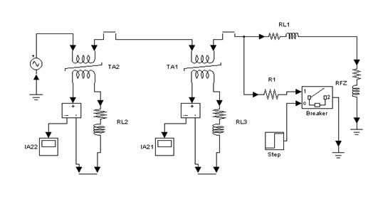
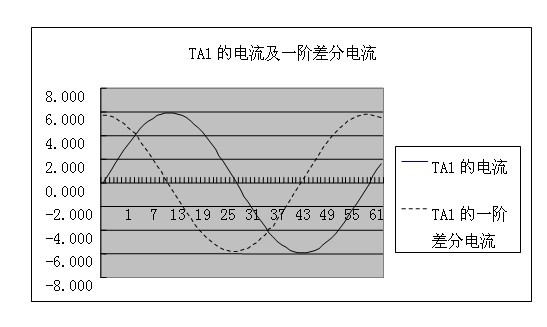
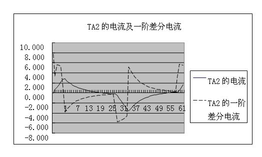

Image

  • Method for judging and compensating current transformer saturation
  • Method for judging and compensating current transformer saturation
  • Method for judging and compensating current transformer saturation

Examples


Embodiment Construction

[0049] In order to make the purpose, technical solution, and advantages of the present invention clearer, the present invention will be described in further detail below with reference to the accompanying drawings.

[0050] The current transformer saturation discrimination and compensation method of the present invention consists of the following steps:

[0051] First, judge whether the instantaneous value of the current satisfies the discrimination condition that the current transformer needs to be saturated;

[0052] Then, if the instantaneous value of the current satisfies the judging condition that the current transformer needs to be saturated, then the saturation judgment of the current transformer is performed;

[0053] Finally, when it is judged that the current transformer is saturated, the polarity and value of the instantaneous current value are compensated.

[0054]The specific steps are: the first step: judge whether the instantaneous value of the current satisfie...


PUM


Abstract

The invention discloses a method for judging and compensating current transformer saturation. The method comprises the following steps of: firstly, judging whether an instantaneous value of current satisfies the condition for judging the saturation need of a current transformer or not; secondly, judging current transformer saturation if the instantaneous value of the current satisfies the condition for judging the saturation need of the current transformer; and at last, performing polarity and numerical compensation on the instantaneous value of the current when the current transformer is saturated according to judgment. Due to the adoption of the method for judging and compensating the current transformer saturation, the current transformer saturation of the current transformer secondarycurrent which attenuates according to an exponential law characteristic can be identified rapidly, and numerical and phase compensation can be performed on the current transformer saturation under the condition. By adopting the method disclosed by the invention, the polarity of fault component instantaneous current and the phase of a fault component current vector can be judged correctly, the protection of a phase comparison principle is not influenced by the current transformer saturation, and the rapidness, sensitivity, reliability and selectivity of phase comparison protection can be improved.

Description

technical field [0001] The present invention relates to the technical field of electric power system relay protection, in particular to a method of phase and numerical compensation for the discrimination of current transformer saturation and how to perform phase and numerical compensation after the current transformer is saturated in the relay protection of the phase comparison principle. Influence on the action behavior of relay protection based on phase comparison principle. Background technique [0002] At present, there are mainly the following methods for judging the saturation of current transformers: [0003] (1) Synchronous identification method. This method is that when an out-of-area fault occurs, there is a linear transmission area at the initial moment of the fault. In this area, the differential protection does not operate, but the starting element must act. When the current transformer is saturated, the difference Only when the dynamic protection can be activa...

Claims


Application Information

Patent Timeline
IPC IPC(8): H02H7/00G01R31/02
Inventor 郭光荣
Owner CHONGQING ELECTRIC POWER COLLEGE
Why Eureka
Try Eureka