Eureka AIR delivers breakthrough ideas for toughest innovation challenges, trusted by R&D personnel around the world.

Novel comprehensive power monitor and installation device and installation method thereof

A power monitor and a new type of technology, applied in circuit devices, electrical components, etc., can solve the problems of unfriendly display interface, low data acquisition rate, poor measurement accuracy, etc., and achieve rich interface display, high measurement accuracy, and fast acquisition speed. Effect

Inactive Publication Date: 2012-01-18
NANTONG LINYANG ELECTRIC CO LTD
View PDF2 Cites 5 Cited by
  • Summary
  • Abstract
  • Description
  • Claims
  • Application Information

AI Technical Summary

Problems solved by technology

[0005] Analyzing similar measurement and control equipment produced at home and abroad, most of them have the following deficiencies: incomplete functions, poor measurement accuracy, and low degree of automation; low data acquisition rate, and cannot intelligently process data; most monitoring products only provide one-way communication interface, and can only support a single communication protocol, which is not conducive to multi-channel data transmission; the expansion function is not rich enough, such as the limited number of switch input channels, which cannot meet the requirements for as many switch signal acquisitions as possible; it is not easy to directly drive one switch device action; The display interface is not friendly, which is not conducive to viewing various measurement data and programming operations on site; it is inconvenient to install, low in efficiency, and a large amount of engineering

Method used


Image

  • Novel comprehensive power monitor and installation device and installation method thereof
  • Novel comprehensive power monitor and installation device and installation method thereof
  • Novel comprehensive power monitor and installation device and installation method thereof

Examples


Embodiment Construction

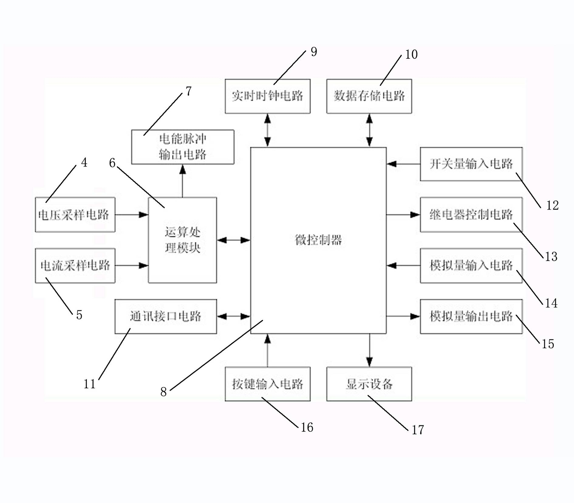
[0021] like figure 1 As shown, a novel comprehensive power monitoring instrument of the present invention includes a voltage sampling circuit 4 and a current sampling circuit 5, and the voltage sampling circuit 4 and the current sampling circuit 5 are all connected to an operation processing module 6, and the operation processing module 6 It is connected with the electric energy pulse output circuit 7, and the operation processing module 6 is also connected with the micro-controller 8, and the micro-controller 8 is connected with the real-time clock circuit 9, the data storage circuit 10 and the communication interface circuit 11 respectively, and the micro-controller The device 8 is also connected with the switch input circuit 12, the relay control circuit 13, the analog input circuit 14, the analog output circuit 15, the key input circuit 16 and the display device 17.

[0022] The operation processing module 6 adopts the ADE7878 electric energy metering chip, which is a thre...


PUM


Abstract

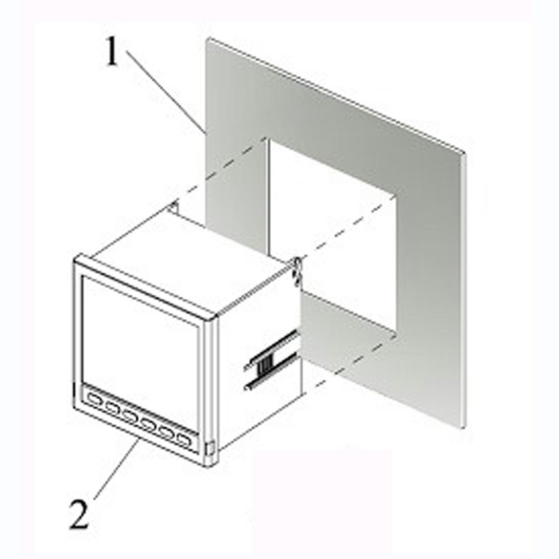
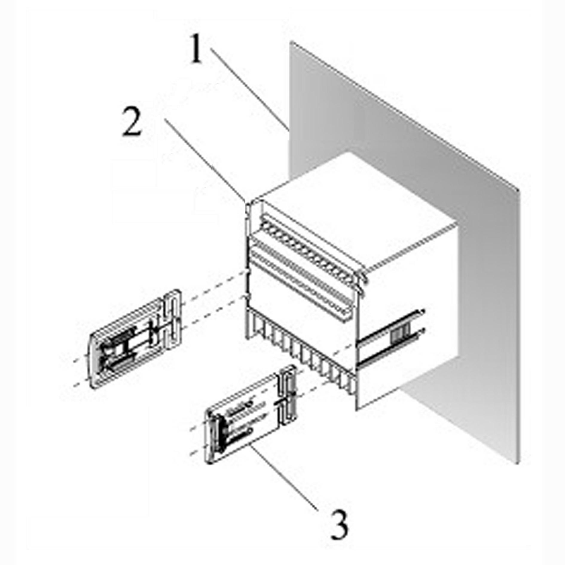
The invention discloses a novel comprehensive power monitor and an installation device and an installation method thereof; the novel comprehensive power monitor comprises a voltage sampling circuit and a current sampling circuit; the voltage sampling circuit and the current sampling circuit are connected with an operation processing module; the operation processing module is connected with an electricity pulse output circuit; the operation processing module is connected with a micro controller; the installation device of the novel comprehensive power monitor comprises a shell body and two fixed clamp frames; the shell body is fixed on an installation screen through the two fixed clamp frames; and the installation method of the novel comprehensive power monitor comprises the steps that: the shell body is fixed on the installation screen through the two fixed clamp frames; the fixed clamp frames are removed; the shell body is inserted into a prepared installation hole; the fixed clamp frames are re-assembled; and then the fixed clamp frames are firmly pressed onto the installation screen. The invention has the advantages of high measuring precision, high acquisition speed, reliable performance, comprehensive functions, rich interface display, compact structure and convenience in use.

Description

technical field [0001] The invention relates to the field of electric power measurement, in particular to a novel integrated electric power monitor. [0002] The invention relates to a new type of installation device for a comprehensive power monitoring instrument. [0003] The invention also relates to a novel comprehensive power monitor installation method. Background technique [0004] The current power measurement products, especially the intelligent monitoring instruments of the transformation and distribution network, need to collect, measure, control and human-computer interaction for the data of the transformation and distribution network, and can transmit the data long-distance through communication to realize the power grid. Intelligent monitoring. [0005] Analyzing similar measurement and control equipment produced at home and abroad, most of them have the following deficiencies: incomplete functions, poor measurement accuracy, and low degree of automation; low...

Claims


Application Information

Patent Timeline
IPC IPC(8): H02J13/00
Inventor 李芳陶培琪
Owner NANTONG LINYANG ELECTRIC CO LTD
Why Eureka
Eureka Blog
Learn More