Autoanalyzer

A technology of automatic analysis device and moving distance, which is applied in the direction of measuring devices, analysis materials, instruments, etc., and can solve problems such as fluctuations in detection results

Active Publication Date: 2012-01-18
HITACHI HIGH-TECH CORP
View PDF9 Cites 15 Cited by
  • Summary
  • Abstract
  • Description
  • Claims
  • Application Information

AI Technical Summary

Problems solved by technology

[0006] In the above-mentioned electrostatic capacitance method, it is necessary to accurately measure the tiny electrostatic capacitance between the dispensing probe and the liquid sample. Th...

Method used


Image

  • Autoanalyzer
  • Autoanalyzer
  • Autoanalyzer

Examples


Embodiment Construction

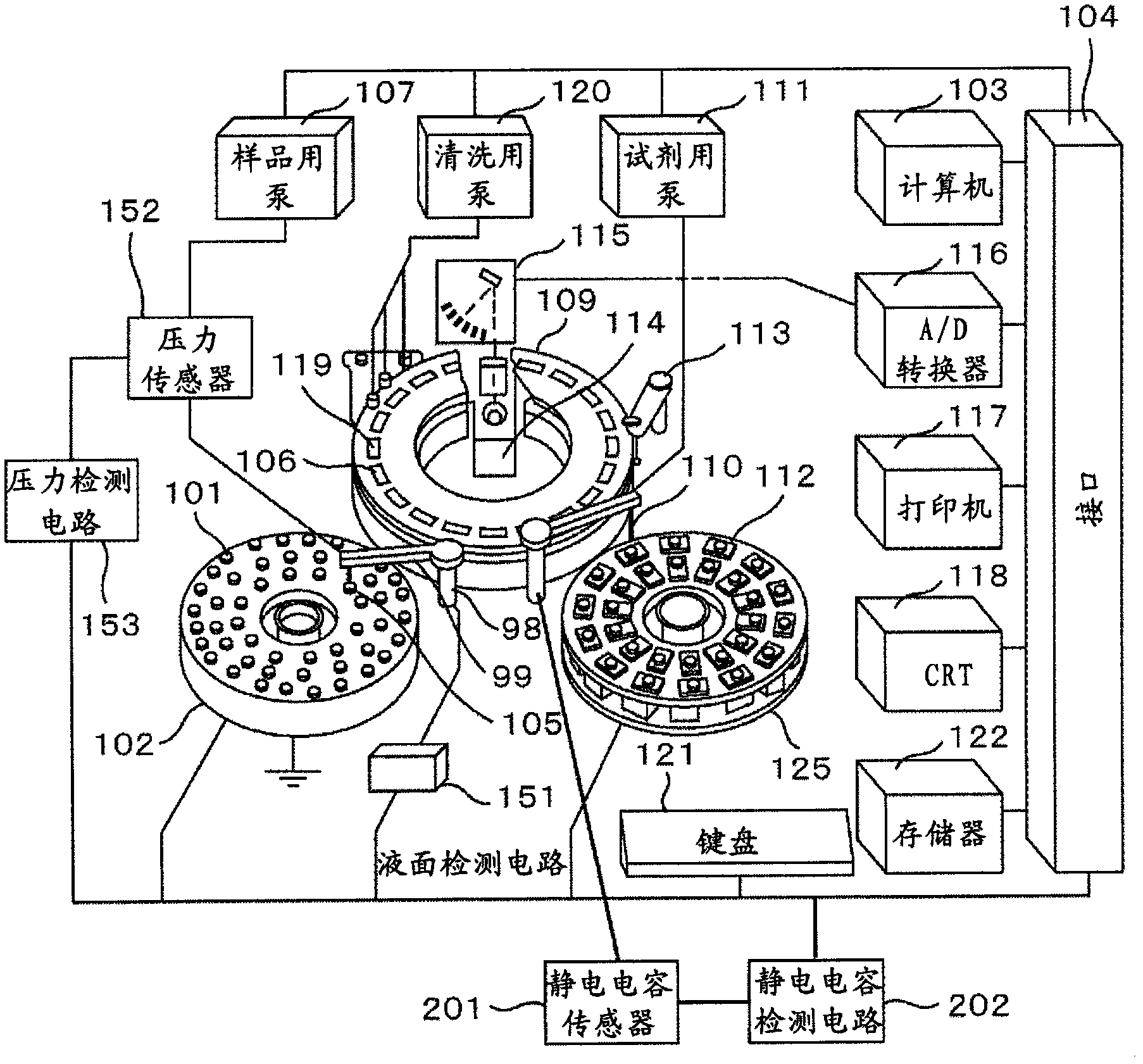
[0037] Below, the embodiment of the present invention is from figure 1 Start in sequence. figure 1 It is a schematic diagram of the automatic analyzer to which the present invention is applied, and shows the dispensing mechanism and its peripheral parts. The structure and function of each part are common to those of conventional automatic analyzers, so detailed descriptions are omitted. The sample dispensing arm 99 of the sample dispensing mechanism 98 rotates while moving up and down. The sample in the sample container 101 arranged on the sample disk 102 rotating left and right is sucked by the probe 105 attached to the sample dispensing arm 99 and discharged into the reaction container 106 . It should be noted that the tip side of the probe 105 is designed such that the nozzle that sucks and ejects the sample hangs down.

[0038] As can also be seen from this figure, the arrangement of the sample container 101 on the sample tray 102 is generally applicable to the case whe...


PUM


Abstract

Provided is an autoanalyzer which is equipped with a reagent disc having a plurality of reagent containers mounted thereon and performs qualitative/quantitative analysis of a living body sample such as blood or urine, wherein measurement error of the liquid level of reagent caused by swinging of the liquid surface incident to rotary operation of the reagent disc is reduced. Assuming a predetermined cycle time is one unit, the reagent disc having the reagent containers mounted thereon is transported to a liquid level detection position using two units or more when the liquid level of the reagent is measured.

Description

technical field [0001] The present invention relates to a liquid level detection mechanism for detecting the liquid level of a liquid sample in an automatic analysis device, in particular to a liquid level detection mechanism for detecting the liquid level based on the change of electrostatic capacitance when a reagent probe touches the liquid surface. Background technique [0002] In liquid level detection mechanisms suitable for clinical automatic analyzers, structures in which a liquid level detection function is added to a dispensing probe are becoming common in response to demands for further improvement in the accuracy of measurement data. As the liquid level detection function of the probe, a probe in which the probe itself is used as an electrode for liquid level detection by utilizing capacitance is known recently. [0003] This capacitance method is to measure the tiny capacitance change between the dispensing probe and the liquid sample contained in the container,...

Claims


Application Information

Patent Timeline
IPC IPC(8): G01N35/04G01N35/02
CPCG01N35/1002G01F23/00G01N35/1009G01N35/025G01N2035/0443G01F23/263G01N2035/1025G01N2035/00673
Inventor 渡边厚志松原茂树山野晃大
Owner HITACHI HIGH-TECH CORP
Why Eureka
Try Eureka