
Computerized flat knitting machine fault detection system

A computerized flat knitting machine and fault detection technology, used in textiles, papermaking, knitting, etc., can solve the problems of computerized flat knitting machines prone to failure, machine destruction, and catastrophic accidents.

Inactive Publication Date: 2012-01-25
浙江汉菲针织机械有限公司
View PDF6 Cites 8 Cited by
  • Summary
  • Abstract
  • Description
  • Claims
  • Application Information

AI Technical Summary

Problems solved by technology

[0003] Computerized flat knitting machines are prone to failures during long-term work, mainly because of the striker fault between the needle and the needle plate. If the striker fault is serious, there may even be catastrophic accidents such as machine destruction. Fault detection in real time
[0004] In the prior art, multiple shock sensors are usually distributed on the needle bed, and the shock sensor detects the vibration shock signal on the needle bed. When the vibration intensity of a certain point exceeds the standard, it can be determined that a striker fault has occurred, but the needle bed and machine head The system constituted is a variable structure system, where the position of the needle plate changes. Therefore, the signal characteristics transmitted to each sensor by the vibration of normal operation or striker fault operation are closely related to the position of the needle plate. The fault diagnosis method adopts a single fixed basis for judging whether the vibration intensity exceeds the standard regardless of the operation status of the machine head, which is prone to missed or misjudged phenomena; Missed judgment phenomenon, failure to detect the real firing pin failure in time, prone to further serious accidents, and even catastrophic accidents

Method used


Image

  • Computerized flat knitting machine fault detection system
  • Computerized flat knitting machine fault detection system

Examples


Embodiment Construction

[0016] In order to enable those skilled in the art to better understand the technical solutions of the present invention, the present invention will be further described in detail below in conjunction with the accompanying drawings and specific embodiments.

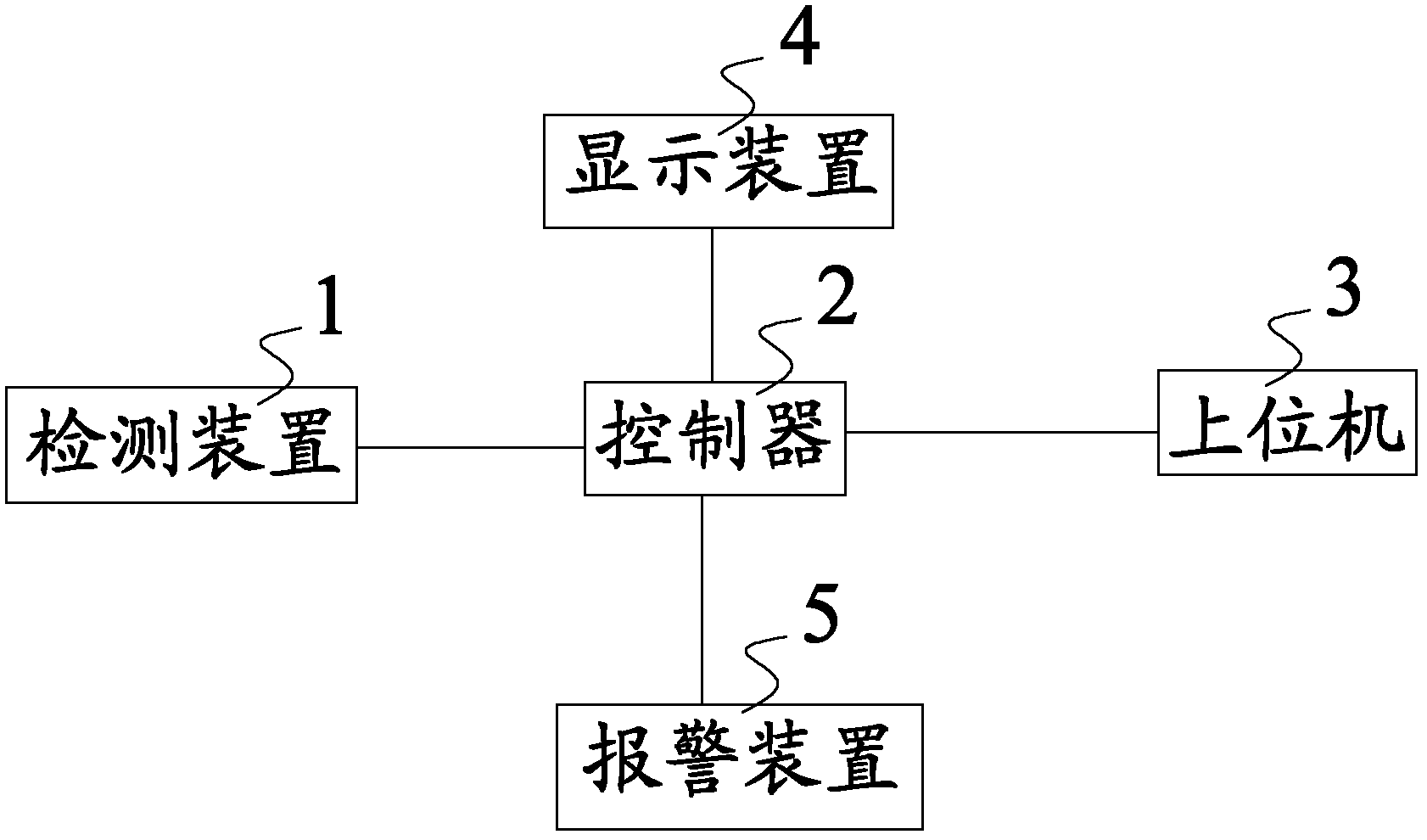
[0017] Please see figure 1 , figure 1 It is a structural schematic diagram of a specific embodiment of the computerized flat knitting machine fault detection system provided by the present invention.

[0018] Please see figure 1 , figure 1 It is a structural schematic diagram of a specific embodiment of the computerized flat knitting machine fault detection system provided by the present invention.

[0019] Such as figure 1 As shown, the computerized flat knitting machine fault detection system provided by the present invention includes a detection controller 2, a host computer 3, an alarm device 5, a display device 4 and a plurality of detection devices 1, and the detection devices 1 are evenly distributed along the ...


PUM


Abstract

The invention relates to the technical field of computerized flat knitting machines, and discloses a computerized flat knitting machine fault detection system. The system comprises a detection controller, an upper computer, an alarm device, a display device and a plurality of detection devices. The detection devices are uniformly arranged on a needle board along the length direction of the needle board, and the detection devices are used for detecting vibration amplitude of the needle board, and sending a vibration amplitude signal to the controller; the controller receives the vibration amplitude signal, compares the detected vibration amplitude with a preset value, if the vibration amplitude is greater than the preset value, the controller judges that the computerized flat knitting machine malfunctions, and the controller sends a fault signal to the upper computer, the upper computer receives the fault signal and controls the computerized flat knitting machine to stop working; if the vibration amplitude is greater than the preset value, the controller sends an alarming signal to the alarm device; and if the vibration amplitude is greater than the preset value, the controller sends the alarming signal and the position information of the detection device to the display device.

Description

technical field [0001] The invention relates to the technical field of computerized flat knitting machines, in particular to a computerized flat knitting machine fault detection system capable of real-time detection of faults in the computerized flat knitting machine. Background technique [0002] A computerized flat knitting machine is a common knitting machine, which usually includes a transmission mechanism, a cloth winding mechanism, a needle selector, a needle plate mechanism, and a cam mechanism. The cam device of the computerized flat knitting machine is like a set of plane cams. The stitches of the knitting needles can enter the grooves of the cams, move the cams, and force the knitting needles to move up and down regularly in the needle grooves of the needle board, and through the needle hook and the needle With the action of the tongue, the yarn can be woven into a knitted fabric. When the knitting needle is rising, the coil gradually withdraws from the needle hoo...

Claims


Application Information

Patent Timeline
Patent Type & Authority Applications(China)
IPC IPC(8): D04B35/18
Inventor 鲁文杰
Owner 浙江汉菲针织机械有限公司
Learn More