Light mixing type monochromatic light source with function of fluorescent powder excitation and projection optical engine using same

A monochromatic light source and phosphor technology, applied in the field of projection optical engines, can solve the problems of shortening the service life of the light source, limiting the development of liquid crystal projection, and high cost of liquid crystal projection, achieving good projection display effect, improving light output purity, and simple structure. Effect

Inactive Publication Date: 2012-01-25
BUTTERFLY TECH SHENZHEN
View PDF5 Cites 23 Cited by
  • Summary
  • Abstract
  • Description
  • Claims
  • Application Information

AI Technical Summary

Problems solved by technology

However, the larger the chip area, the higher the driving current, and the greater the heat generated, which often shortens the service life of the light source, and the output of a single chip is also limited; in addition, high-brightness, large-chip LEDs are expensive , so that the production cost of the light source is relatively high, which in turn leads to relatively high cost of liquid crystal projection, which limits the development of liquid crystal projection

Method used


Image

  • Light mixing type monochromatic light source with function of fluorescent powder excitation and projection optical engine using same
  • Light mixing type monochromatic light source with function of fluorescent powder excitation and projection optical engine using same
  • Light mixing type monochromatic light source with function of fluorescent powder excitation and projection optical engine using same

Examples


Embodiment Construction

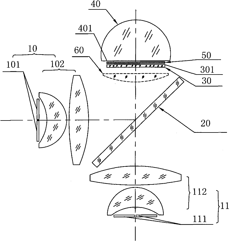
[0018] figure 1 Shown is a schematic diagram of the planar structure of the mixed-light monochromatic light source with phosphor excitation according to the first embodiment of the present invention, which includes a first pump light source module 10, a second pump light source module 11, a color combining mirror 20, A filter 30 , an optical lens 40 and a phosphor layer 50 .

[0019] The first pumping light source module 10 emits the first pumping light, which includes a first light-emitting chip 101 and a first light source shaping mirror group 102 for collecting and shaping the first pumping light. The second pumping light source module 11 emits the second pumping light (the peak wavelength of the second pumping light is different from the peak wavelength of the first pumping light), which includes a second light-emitting chip 111 and a The second light source shaping mirror group 112 for the second pump light. In the embodiment of the present invention, both the first lig...


PUM


Abstract

A light mixing type monochromatic light source with the function of fluorescent powder excitation function comprises a first pumping light source module for emerging first pumping light, a second pumping light source module for emerging second pumping light, a color combination mirror, a light filter, a fluorescent powder layer and an optical lens, wherein the light filter, the fluorescent powder layer and the optical lens are arranged in sequence. The fluorescent powder layer is used for absorbing the first pumping light and the second pumping light and exciting the fluorescent light whose wavelength is different from that of the first pumping light and that of the second pumping light. A first thin film is coated on the surface of the optical lens facing to the fluorescent powder layer and is used for transmitting the fluorescent light and reflecting the first pumping light and the second pumping light. A second thin film is coated on the surface of the light filter facing to the fluorescent powder layer and is used for transmitting the first pumping light, the second pumping light and reflecting the fluorescent light. The monochromatic light source increases the excitation energy of fluorescent powder in a manner of mixing the two pumping lights, thereby increasing the emergence brightness of the fluorescent light. Compared with the traditional large chip, the light mixing type monochromatic light source has low cost and increases the power of finally-emerged monochromatic light. In addition, the invention also provides a projection optical engine using the light mixing type monochromatic light source.

Description

technical field [0001] The invention relates to a light source and projection display technology based on phosphor powder excitation, in particular to a light-mixing monochromatic light source with phosphor powder excitation and a projection optical engine using the same. Background technique [0002] The light source is one of the most important parts of the LCD projector. Its brightness, light utilization rate and heat generation directly affect the quality of the projected image, the power consumption of the projector, the use and maintenance cost of the projector and other issues. In the past, most projectors used ultra-high pressure mercury lamps (UHP) or metal halide lamps as light sources. Although the brightness of such light sources can meet the requirements, they have high energy consumption and short life, low light conversion efficiency, and high heat generation. And it will pollute the environment, so it is not very suitable for use as a projection light source....

Claims


Application Information

Patent Timeline
Patent Type & Authority Applications(China)
IPC IPC(8): F21K2/00F21V13/00F21V17/00G03B21/20G02B27/18G03B21/00
Inventor 曲鲁杰黄鹏廖深财
Owner BUTTERFLY TECH SHENZHEN
Why Eureka
Try Eureka