Fixture for positioning and broaching bevel gear tooth surface

A bevel gear and tooth surface technology, which is applied in the field of bevel gear tooth surface positioning broaching fixtures, can solve the problems of being unsuitable for mass production, consuming a lot of man-hours, and low work efficiency, and achieving easy clamping, high production efficiency, and positioning. simple structure

Inactive Publication Date: 2012-02-01
JIANGSU AIRSHIP GEAR
View PDF0 Cites 10 Cited by
  • Summary
  • Abstract
  • Description
  • Claims
  • Application Information

AI Technical Summary

Problems solved by technology

However, in the prior art, it takes a lot of man-hours to mill the shoulders on both sides separately, and the work efficiency is low, so it is not suitable as a machining method for mass production

Method used


Image

  • Fixture for positioning and broaching bevel gear tooth surface
  • Fixture for positioning and broaching bevel gear tooth surface
  • Fixture for positioning and broaching bevel gear tooth surface

Examples


Embodiment Construction

[0014] The present invention will be further described below according to the accompanying drawings and in conjunction with the embodiments.

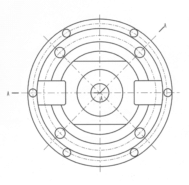
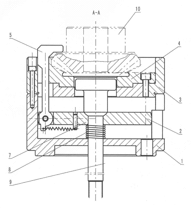
[0015] figure 1 Shown is the embodiment of the bevel gear tooth surface positioning broaching jig, and the elongated boss on the back of the broaching gear. The fixture is composed of two parts: a positioning structure and a clamping structure. The positioning structure includes a chassis 1, a positioning seat 3 and a tooth mold 4 that are coaxially stacked and connected in sequence from bottom to top. The chassis 1 at the bottom is positioned on the workbench with a seam, and the tooth mold 4 is placed on the positioning seat. 3. Position with seam. The clamping structure is built in the positioning structure, and it includes a slide block 2, an angle buckle 5, a tension spring 6, a pin 7, a compression spring 8 and a pull rod 9. The slider 2 is placed between the chassis 1 and the positioning seat 3, and the outer contours of the s...


PUM


Abstract

The invention discloses a fixture for positioning and broaching a bevel gear tooth surface, comprising a positioning structure and a clamping structure, wherein the positioning structure comprises a chassis, a positioning seat and a tooth die which are successively overlaid and connected from bottom to top; the clamping structure comprises a sliding block, an angle buckle, a tension spring, a pin, a pressure spring and a draw bar; the sliding block is built in an inner cavity between the chassis and the positioning seat; the outer outlines of the sliding block and the positioning seat are provided with two opening slots with symmetrical structure; the opening slot in the sliding block is hinged with the angle buckle; two ends of the tension spring are respectively connected with the lower end of the angle buckle and the pin to form an elastic tension structure; and the draw bar is penetrated from the inner hole of the tooth die to be connected with the positioning seat, the sliding block, the pressure spring and the chassis in series in sequence to form the structure that the draw bar and the pressure spring guide the sliding block to drag the angle buckle to axially slide. In the fixture, the tooth die positioning structure is adopted, and therefore the fixture is accurate and reliable to position. After a workpiece is installed, the workpiece is directly meshed with the teeth of the tooth die, the pitch cercle of the tooth die serves as the positioning reference which is same with a design reference, and therefore positioning errors can be prevented from generating.

Description

technical field [0001] The invention relates to a machining fixture, in particular to a bevel gear tooth surface positioning and broaching fixture. Background technique [0002] The bevel gear is a transmission part in the automobile transmission. The side with bevel teeth is the front, and the back is provided with a long strip boss. The boss is the positioning reference of the bevel gear on the installation position, and its position tolerance directly affects the installation quality. In the industry, the front bevel teeth are usually used for positioning, axial compression, and then the milling process is used to realize the forming process of the long strip convex surface. Although the prior art has accurate positioning and reliable clamping, it can realize precise forming processing. However, in the prior art, it takes a lot of man-hours to mill the shoulders on both sides separately, and the work efficiency is low, so it is not suitable as a machining method for mas...

Claims


Application Information

Patent Timeline
Patent Type & Authority Applications(China)
IPC IPC(8): B23Q3/00
Inventor 葛珍小
Owner JIANGSU AIRSHIP GEAR
Why Eureka
Try Eureka