Method for installing rotary vane type steering engine

A technology of turning vane steering gear and steering gear, which is applied in the direction of steering, transportation and packaging, and ship parts with rudder, can solve the problems of oil leakage of steering gear, deformation of hull, complicated installation process, etc., so as to improve work efficiency and increase The effect of space height and accident risk reduction

Active Publication Date: 2012-02-01
YICHANG DAMEN SHIP
View PDF7 Cites 13 Cited by
  • Summary
  • Abstract
  • Description
  • Claims
  • Application Information

AI Technical Summary

Problems solved by technology

[0004] In the prior art, such as figure 2 As shown in , usually the steering gear bushing is installed on the rudder stock first, and then the steering gear is installed. The problem is: if the main building, such as the upper cabin, is fully installed before installing the steering gear, then The space in the cabin is small, and it is impossible to lift the steering gear to the rudder stock. Even if it can be installed barely, because the weight of the steering gear reaches more than 2T, each lifting device is mostly in a state of parallel stress, and the stress state is bad, which is prone to safety hazards. ACCIDENT
The installation process is complicated and time-consuming
Occasionally, the bushing and the steering gear are not well fitted, causing oil leakage accidents when pressing the steering gear, resulting in installation failure
[0005] If the steering gear is installed before the main building is installed, after the main building is installed, the hull will be deformed due to the influence of the superstructure, which will affect the accuracy of the steering gear, especially the axis of the rudder line and the propeller. Not vertical, affecting the overall installation quality of the ship

Method used


Image

  • Method for installing rotary vane type steering engine
  • Method for installing rotary vane type steering engine
  • Method for installing rotary vane type steering engine

Examples


Embodiment Construction

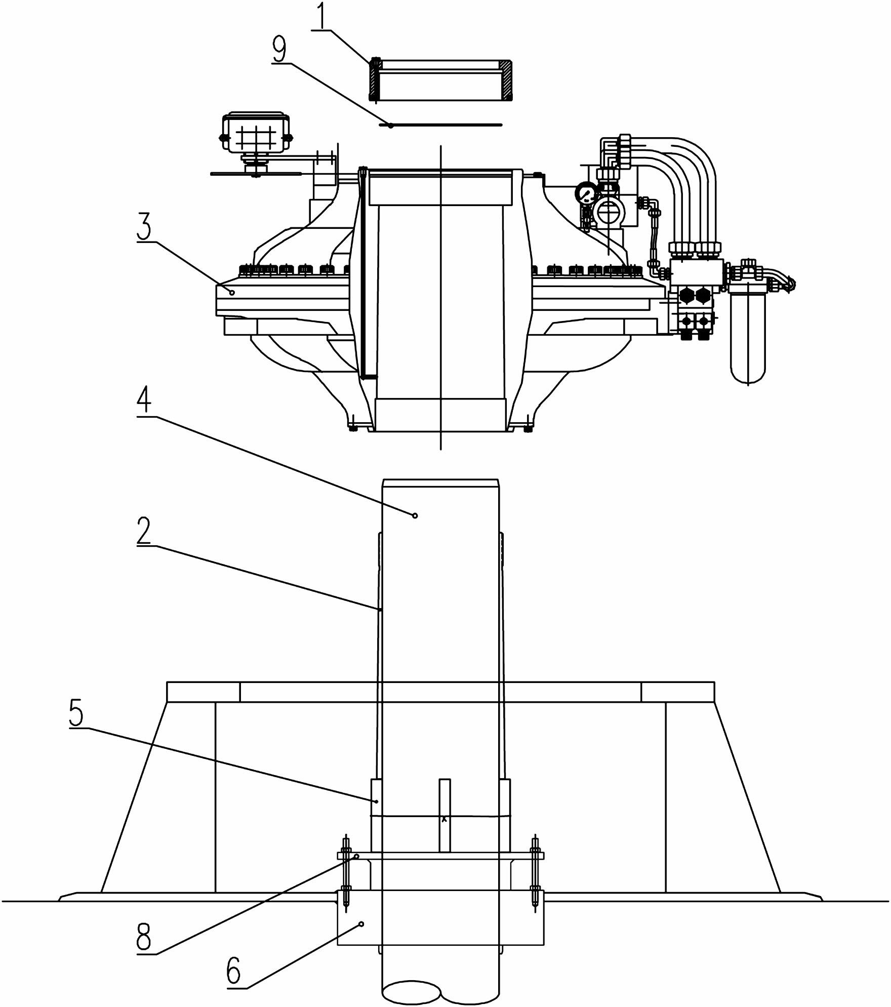
[0028] A method for installing a rotary vane steering gear, comprising the following steps:

[0029] A. If image 3 As shown in , place the steering gear bushing 2 in the steering gear 3, install the bushing top sealing ring 9 and the bushing hydraulic nut 1, the bushing hydraulic nut 1 cannot be tightened, that is, the outer wall of the steering gear bushing 2 must be in contact with the rudder There is a certain gap between the inner holes of the machine 3 to facilitate subsequent installation;

[0030] B. Move the rudder stock 4 downward until there is enough space above the rudder stock 4 to install the steering gear 3; in order to ensure the smooth settlement of the rudder stock 4, the bearing stuffing box 6 and stuffing box cover 8 cannot be installed at this time, and the bearing stuffing box 6 And stuffing box cover plate 8 just is enclosed within on the rudder stock 4.

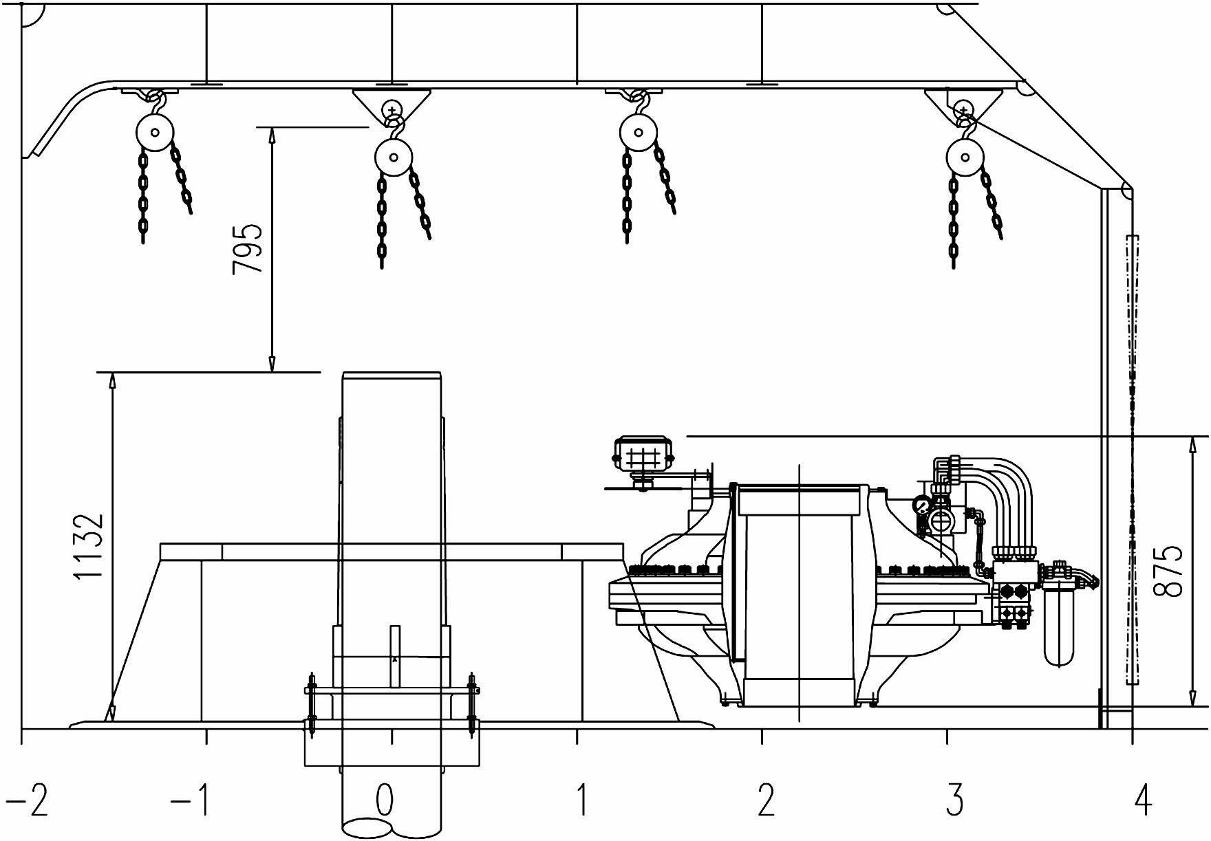
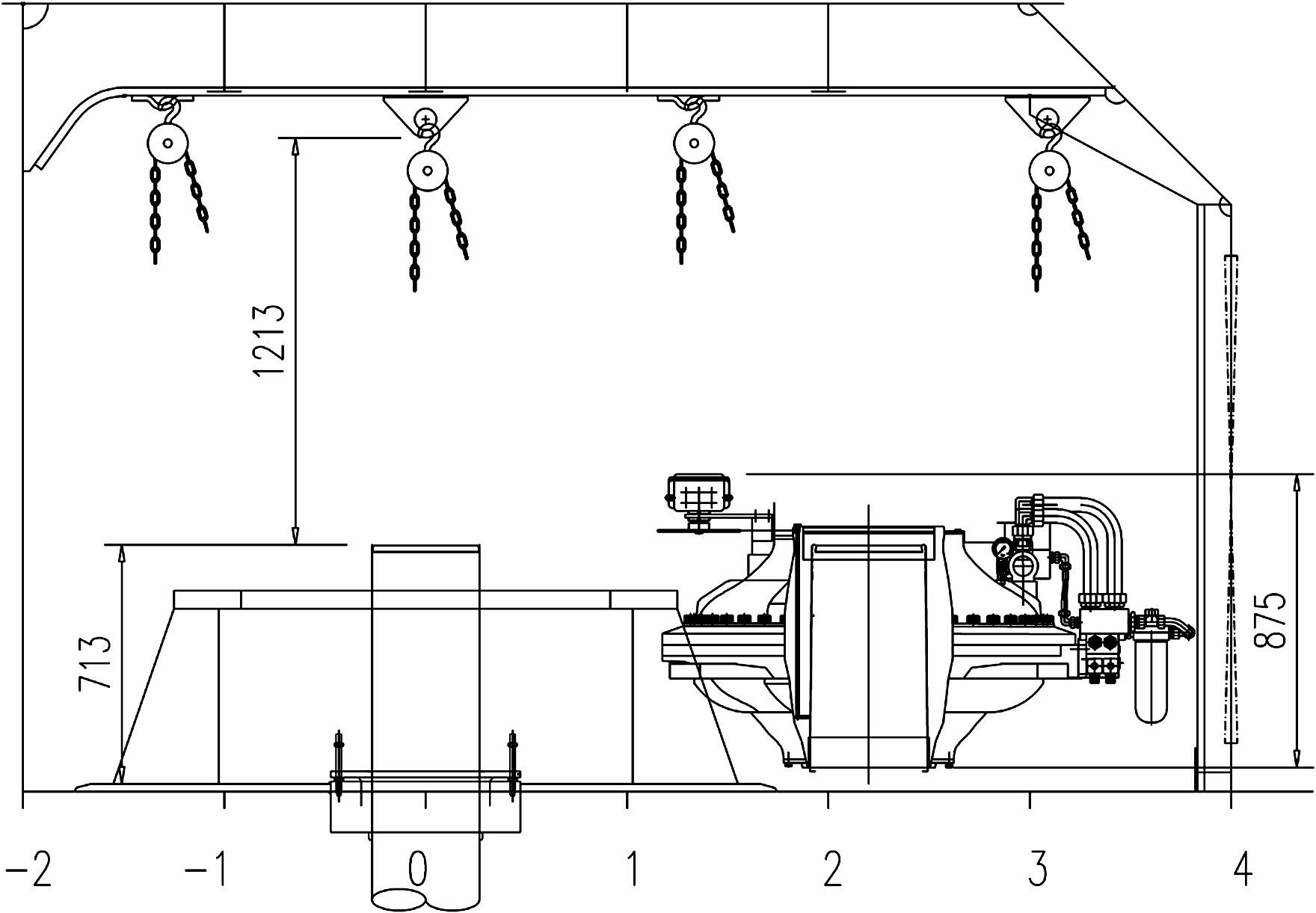
[0031] C. When the steering gear 3 is above the rudder stock 4, pull up the rudder stock 4 until...


PUM


Abstract

The invention provides a method for installing a rotary vane type steering engine. The rotary vane type steering engine is installed in a narrow space by using a method comprising the following steps of: combining the steering engine with a steering engine bushing at first, then lowering a rudderstock and integrally lifting the steering engine, and finally, lifting the rudderstock; the non-vertical quality problem of a rudder line and the axis of a propeller resulted from the installation of the steering engine before a main body building is installed can be avoided; or the difficult installation problem of the steering engine in the narrow space after the main body building is installed can be avoided; the installation space height of the steering engine is increased; the stress condition of a chain hoist in the event of transferring the steering engine can be improved; therefore, the accident risk can be reduced; because the steering engine bushing is placed on a bushing support in the event of installing, the steering engine and the steering engine bushing are tightly combined; therefore, the oil leakage fault can be avoided in the event of injecting hydraulic oil; in the priorart, the whole steering engine is installed for 2-2.5 days; but, the steering engine is installed only for 1-1.5 days by using the method disclosed by the invention; therefore, the working efficiencyis increased.

Description

technical field [0001] The invention relates to a method for installing marine equipment, in particular to a method for installing a rotary blade steering gear in a narrow space. Background technique [0002] The rotary vane steering gear is a kind of hydraulic steering gear. Its shape resembles a flying saucer, also known as a dish-shaped steering gear. Its working principle: the built-in hydraulic pump on the steering gear presses the hydraulic oil into the annular oil cylinder, and the rotor blade in the oil cylinder transmits the torque to the rudder stock to achieve the purpose of turning the rudder. [0003] Such as figure 1 Among them, the core of the installation of the rotary blade steering gear is the installation steering gear bushing 2 that comes with the steering gear. The inner diameter of the steering gear bushing 2 is 0.1-0.2mm larger than the outer diameter of the rudder stock 4, so that it can be placed on the rudder stock. The outer surface of the stee...

Claims


Application Information

Patent Timeline
Patent Type & Authority Applications(China)
IPC IPC(8): B63B9/00B63H25/26
Inventor 陈义武
Owner YICHANG DAMEN SHIP
Why Eureka
Try Eureka