
Two-way screw conveying device

A conveying device, bidirectional spiral technology, applied in the field of lead powder conveying device, to achieve the effects of reduced coaxiality error, reduced load, and reliable operation

Inactive Publication Date: 2012-02-01
JIANGSU SANHUAN IND HLDG CO LTD
View PDF5 Cites 6 Cited by
  • Summary
  • Abstract
  • Description
  • Claims
  • Application Information

AI Technical Summary

Problems solved by technology

It is mainly composed of a geared motor 1, a driving component 2, a discharge port 3, a screw shaft 4, a feed port 5, a spiral blade 6, a suspension bearing 7, a cover plate 8, a casing 9 and a driven component 10. It passes through The motor drives the screw shaft 4 to rotate, and the rigid helical blade 6 on the rotating shaft 4 pushes the lead powder to transport the lead powder, but only one-way delivery of the lead powder can be realized

Method used


Image

  • Two-way screw conveying device
  • Two-way screw conveying device
  • Two-way screw conveying device

Examples


Embodiment Construction

[0017] The present invention will be further described below in conjunction with accompanying drawing.

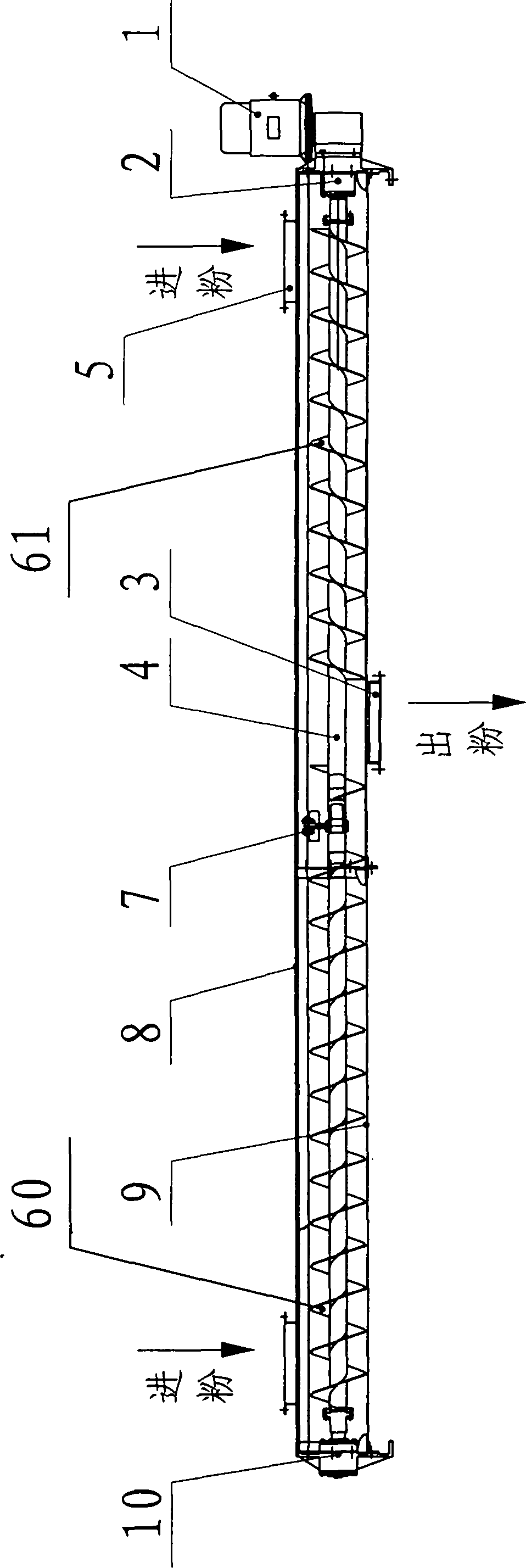
[0018] A two-way screw conveying device, including a geared motor 1, a drive assembly 2, a discharge port 3, a screw shaft 4, a feed port 5, a suspension bearing 7, a casing 9 and a driven assembly 10, the geared motor 1 is located on the machine One end of the shell 9, the driven assembly 10 is located at the other end of the casing 9, the geared motor 1 is connected to one end of the screw shaft 4 through the drive assembly 2, the other end of the screw shaft 4 is connected to the driven assembly 10, and the screw shaft 4 passes through the suspension bearing 7 is fixed, a forward helical blade 60 is provided on one section of the screw shaft 4, and a reverse helical blade 61 is provided on the other section of the helical shaft 4, and the two feed ports 5 are respectively located at the forward helical blade 60 and the reverse helical At the ends of both sides of the rot...


PUM


Abstract

The invention relates to a two-way screw conveying device which comprises a speed reducing motor (1), a driving component (2), a discharge hole (3), a screw shaft (4), feeding holes (5), a hanger bearing (7), a housing case (9) and a driven component (10), and is characterized in that one section of the screw shaft (4) is provided with a positive spiral vane (60), and the other section of the screw shaft (4) is provided with a negative spiral vane (61); the two feeding holes (5) are respectively positioned at the tail ends of the two sides of the positive spiral vane (60) and the negative spiral vane (61); and the discharge hole (3) is positioned between the positive spiral vane (60) and the negative spiral vane (61). The screw shaft is welded with the two sections of vanes with the opposite screw directions, so that lead powder arranged at the two ends of the screw shaft can be conveyed into a middle powder outlet and then is output when the screw shaft is driven to rotate by the motor. The two-way screw conveying device has the advantages that the screw length is reduced, the material is saved, and the cost is reduced; meanwhile, as the screw length is reduced, the screw operation is more reliable.

Description

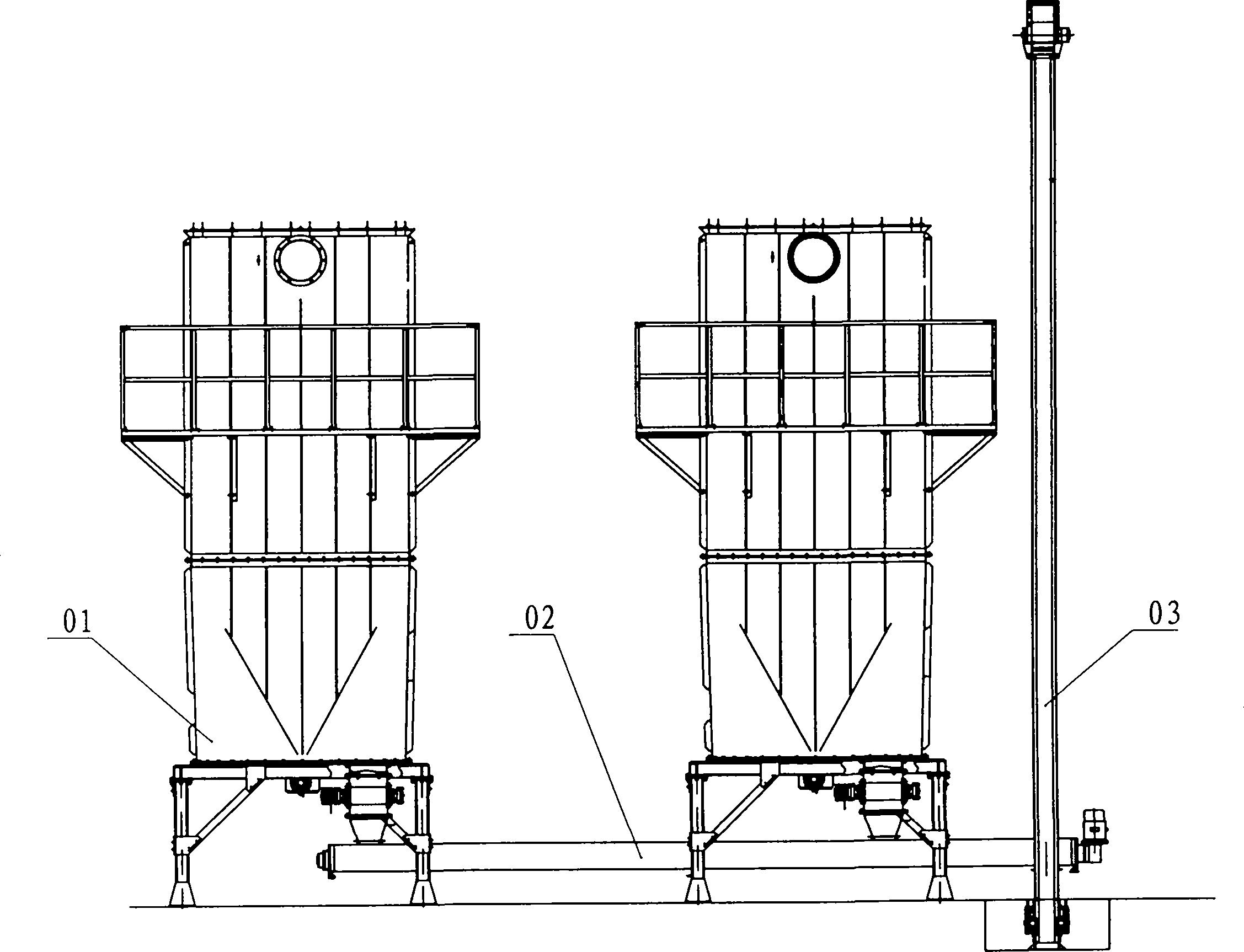
technical field [0001] The invention relates to a lead powder conveying device, in particular to a two-way screw conveying device which realizes two-way conveying of lead powder. The device is mainly used for centralized powder discharge of multiple powder collectors or multiple powder bins. Background technique [0002] Currently, figure 1 The above is a structural schematic diagram of a screw conveyor commonly used in the market for lead powder transportation. It is mainly composed of a geared motor 1, a driving component 2, a discharge port 3, a screw shaft 4, a feed port 5, a spiral blade 6, a suspension bearing 7, a cover plate 8, a casing 9 and a driven component 10. It passes through The motor drives the screw shaft 4 to rotate, and the rigid helical blade 6 on the rotating shaft 4 pushes the lead powder to carry out the delivery of the lead powder, but it can only realize the one-way delivery of the lead powder. figure 2 It is the installation form of the screw co...

Claims


Application Information

Patent Timeline
Patent Type & Authority Applications(China)
IPC IPC(8): B65G33/14B65G33/26
Inventor 王羽王约倪顾金杰史春辉高树名吴恒
Owner JIANGSU SANHUAN IND HLDG CO LTD
Learn More