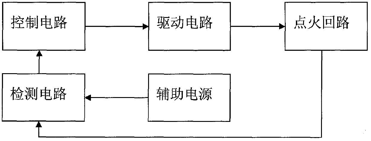
Floating power supply detecting circuit of ignition circuit
A technology for detecting circuits and ignition circuits, applied in electronic circuit testing, measuring electricity, measuring devices, etc., can solve the problems affecting the reliability of ignition circuits, complex circuits and strong switching noise, etc., to reduce the number and types, improve reliability, The effect of simplifying the circuit
- Summary
- Abstract
- Description
- Claims
- Application Information
AI Technical Summary
Problems solved by technology
Method used
Image
Examples
Embodiment 1
[0016] For a certain type of ignition circuit, it is known that the external working power supply voltage is 5V, and the charging power supply is 27V. The task requires that there should be no third DC power supply higher than 5V in the ignition circuit except the power supply in the above state. The voltage collected by the detection circuit is 0V, 5V and 27V. The test output value of the detection circuit is collected by the control circuit only when the input terminal is 0V and 5V. When the input terminal is 27V, the test output value is not collected by the control circuit. collection.
[0017] For the above situation, the present invention can be adopted to supply power to the detection circuit (see image 3 ), when the ignition circuit is in the detection state, the comparator LM139 is powered by the 5V working power supply through the diode V1 (model 1N4148), when the ignition circuit is in the ignition charging state, the 27V power supply at the charging end passes thr...
Embodiment 2
[0019] For a certain type of ignition circuit, it is known that the external working power supply voltage is 5V, and the charging power supply is 27V. The task requires that there should be no third DC power supply higher than 5V in the ignition circuit except the power supply in the above state. like Figure 4 As shown, the detection circuit collects three kinds of voltages: 0V, 5V and 27V. When the detection circuit input is 0V, 5V and 27V, the test output value is collected by the control circuit. When the ignition circuit is in the detection state, the 5V working power supply supplies power to the comparator LM139 through the field effect transistor V3 (model IRF3205SR). When the ignition circuit is in the ignition charging state, the 27V power supply at the charging end passes through the field effect transistor V4 (The model is IRF3205SR) to supply power to the comparator, so that the voltage at the power supply terminal of the comparator is always greater than the volta...
Embodiment 3
[0021] For a certain type of sensor circuit, it is known that the externally detected voltage signals are 5V signal, 12V signal and 28V signal. The detection circuit needs to switch to provide different voltage power supply for the circuit according to the difference of the externally detected voltage signal. like Figure 5 As shown, when the detection voltage signal is 5V, give signal 3 a high level of 5V, and a power supply of 9V supplies power to the circuit through the field effect transistor V5 (model IRF3205SR); when the detection voltage signal is 12V, give signal 4 a high level 5V, power supply 2 15V supplies power to the circuit through FET V6 (model IRF3205SR); when the detection voltage signal is 28V, give signal 5 high level 5V, power supply 2 30V supplies circuit through FET V7 (model IRF3205SR) powered by. In this way, the function of power supply switching is completed.
PUM
| Property | Measurement | Unit |
|---|---|---|
| Resistance | aaaaa | aaaaa |
| Resistance | aaaaa | aaaaa |
Abstract
Description
Claims
Application Information
 - R&D
- Intellectual Property
- Life Sciences
- Materials
- Tech Scout
- Unparalleled Data Quality
- Higher Quality Content
- 60% Fewer Hallucinations
Browse by: Latest US Patents, China's latest patents, Technical Efficacy Thesaurus, Application Domain, Technology Topic, Popular Technical Reports.
© 2025 PatSnap. All rights reserved.Legal|Privacy policy|Modern Slavery Act Transparency Statement|Sitemap|About US| Contact US: help@patsnap.com


