

Energy-saving pre-twisted spacer made of composite materials
A composite material and spacer bar technology, applied in the spacer bar field, can solve the problems of easy loss of spacer bar fasteners, high installation and maintenance difficulty, heavy spacer bar weight, etc., and achieves superior performance, convenient installation and maintenance, and mechanical strength. high effect
- Summary
- Abstract
- Description
- Claims
- Application Information
AI Technical Summary
Problems solved by technology
Method used
Image

Examples
Embodiment 1
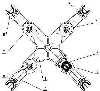
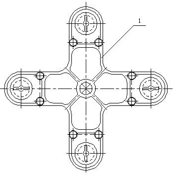
[0027] like figure 1 As shown, this embodiment provides a composite material energy-saving pre-twisted spacer, including a spacer frame 1 and a spacer support arm 2, such as Figure 4 , Figure 6 and Figure 7 As shown, the spacer bar support arm 2 is fork-shaped, and the head of the spacer bar support arm 2 is provided with a waist-shaped half-moon groove 10, a U-shaped groove 11, and is used to pass through the half-moon groove 10, U-shaped The groove 11 wraps the wire and the spacer bar support arm 2 around the fixed pre-twisted wire protection line 9, the U-shaped groove 11 is provided with a non-slip rubber pad 8, and the tail of the spacer bar support arm 2 is provided with a circular hollow Groove 12, the circular hollow groove 12 is provided with a cross shaft sleeve 3 and a rubber column 4, the circular hollow groove 12 and the cross shaft sleeve 3 form a hollow chamber, and the rubber pillar 4 is filled in the hollow chamber , the tail of the spacer bar support ar...
Embodiment 2
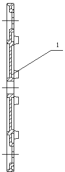
[0029] like Figure 8 As shown, the present embodiment provides a composite material energy-saving pre-twisted spacer, comprising a spacer frame 1 and a spacer support arm 2, the head of the spacer support arm 2 is provided with a half-moon groove 10, a U-shaped concave Groove 11 and the pre-twisted wire protective wire 9 that is used to pass through the half-moon groove 10 and U-shaped groove 11 to wind and fix the wire and the spacer support arm 2. The U-shaped groove 11 is provided with a non-slip rubber pad 8, so The tail of the spacer rod support arm 2 is provided with a circular cavity 12, the circular cavity 12 is provided with a cross sleeve 3 and a rubber column 4, and the circular cavity 12 and the cross sleeve 3 form a hollow space. In the groove chamber, the rubber column 4 is filled in the hollow chamber, and the tail of the spacer rod support arm 2 is connected to the end of the spacer rod frame 1 . The spacer bar frame 1 includes an upper frame and a lower fram...
PUM
 Abstract
Description
Claims
Application Information