Dust removing device applied to pipeline

A technology of a dust removal device and a pipeline, which is applied to the separation of dispersed particles, chemical instruments and methods, separation methods, etc., can solve the problems of the danger of burning, the reduction of dust removal efficiency, the intensification of eddy current, etc., and the effect of simple structure is achieved.

Inactive Publication Date: 2012-02-08
北京德天御投资管理有限责任公司
View PDF10 Cites 4 Cited by
  • Summary
  • Abstract
  • Description
  • Claims
  • Application Information

AI Technical Summary

Problems solved by technology

[0015] The air velocity at the inlet of the cyclone dust collector has a great influence on dust removal. If the air velocity is too low, the dust removal effect will be poor. If the air velocity is too high, the pressure loss will increase and the eddy current will intensify, which will also reduce the dust removal efficiency; There is a danger of burning in the separation of dust with combustible components, so its applicability is limited

Method used


Image

  • Dust removing device applied to pipeline
  • Dust removing device applied to pipeline
  • Dust removing device applied to pipeline

Examples


Embodiment 1

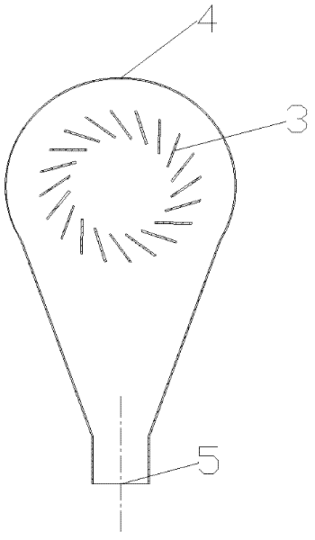
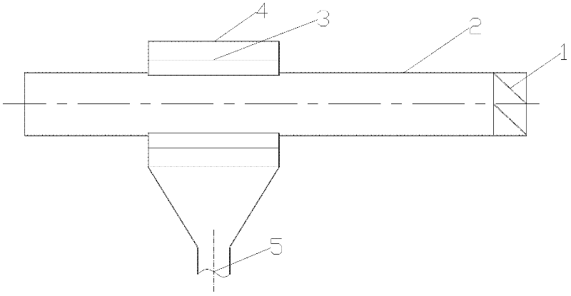
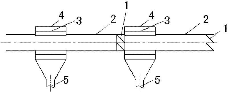
[0045] Embodiment 1: As shown in the figure, a dust removal device used on a pipeline uses the guide fins of the guide part 1 installed inside the pipeline conduit 2 to make the air flow rotate and move the dust to the pipe wall. Dust enters the gap between the gas-solid separation fin 3 and the housing 4 through the action of the gas-solid separation fin 3 of the dust removal part, flows downward under the action of gravity, and is discharged out of the system through the lower ash fall pipe 5 .

Embodiment 2

[0046] Embodiment 2: As shown in the figure, a dust removal device used on a pipeline uses a guide member 1 to rotate the fluid, and the dust-laden gas (liquid) enters the dust removal part through the conduit 2 and under the action of the gas-solid separation fin 3, Dust (liquid droplets) enters the shell 4 through the gap of the gas-solid separation fin 3, enters the ash falling pipe 5 under the action of gravity, and is discharged out of the system to realize dust removal in the pipeline.

[0047] The front and rear of the dust removal device are connected with pipes or conduits 2, which are part of the gas or liquid delivery pipeline.

[0048] The dedusting device can be used in pipelines conveying dusty gas or liquid containing solid particles.

[0049] The container connected to the ash fall pipe 5 at the lower part can be equipment under normal pressure or with pressure, but it must be ensured that the pipeline connected to the dust removal device is a sealed system, an...

Embodiment 3

[0052] A dust removal device used on pipelines. The structure of the guide part 1 of the dust removal device is a plate-shaped structural member that forms a certain angle with the radial section of the duct 2, and is fixed on the inner wall of the duct 2 by welding, inlaying or clamping;

[0053] The structure of the gas-solid separation fin 3 is a rectangular plate 6 according to Figure 8 The layout of the schematic diagram, there is an auxiliary line 7 of a virtual circle (just to illustrate the structure, in fact there is no real object), at the junction of the rectangular plate 6 and the auxiliary line 7, the extension line of the rectangular plate 6 at the joint is in the same shape as the radius line of the virtual circle Distributed at a certain angle a;

[0054] The connection relationship between the shell 4 and the gas-solid separation fin 3 is fixed on the side wall of the shell 4 by means of welding, inlaying or clamping;

[0055] The connection relationship betwe...


PUM


Abstract

The invention discloses a dust removing device applied to a pipeline. A diversion component is connected with a conduit; a gas-solid separating fin is fixed on the side wall of a shell; the conduit is fixedly connected with the shell; both sides of the shell are provided with holes; a hole of the conduit is communicated with the holes of the shell; the gas-solid separating fin and the conduit are arranged concentrically; and the lower end of the shell is connected with a dust falling pipe. The dust removing device is used for removing entrained solid or liquid particles in the conveying process of various gases or liquids containing solid particles or liquid fog drops, so that influences on operation caused by dust or solid (liquid) particles in subsequent processes are reduced. In the invention, a fluid rotates while entering a pipeline through a pipeline embedded structural piece, so that the fluid moves forward spirally; and solid particles or liquid drops with large specific weights move towards a pipe wall side under the action of centrifugal force, move into an outer layer interlayer while passing through the blade gap of a dust removing component, and enter a recovering system under the action of gravity.

Description

technical field [0001] The invention relates to a dust removal device used on pipelines, belonging to the technical field of dust removal and purification. Background technique [0002] The existing dust removal technology mainly uses cyclone dust collector or cloth bag dust removal, or uses the deformation and combination of the first two technologies to achieve dust removal. [0003] The existing dust collector is used alone in the system as a piece of equipment, and its structural form is a straight cylinder at the top and a conical structure at the bottom. The intake air enters in the tangential direction of its upper part, and forms a rotating downward airflow along the inner wall. In the lower part of the cone, due to the gradual reduction in diameter, the rotating airflow shrinks to form an upward rotating airflow and is exported to the dust collector through the upper outlet. The dust or mist contained in the gas Under the action of centrifugal force, it moves towar...

Claims


Application Information

Patent Timeline
Patent Type & Authority Applications(China)
IPC IPC(8): B01D45/16
Inventor 曹振海
Owner 北京德天御投资管理有限责任公司
Why Eureka
Try Eureka