Air pressure brake unit and multi-shaft automobile chassis with same

A technology for pneumatic brakes and multi-axle vehicles, which is applied in the direction of brake transmission, brakes, brake components, etc., and can solve the problems of utilization of adhesion between wheels and the ground, limitation of compressed air flow, and reduction of vehicle driving safety. Ensure the normal function, improve the braking response speed, and ensure the effect of timely effectiveness

Active Publication Date: 2012-02-08
XUZHOU HEAVY MASCH CO LTD
View PDF8 Cites 11 Cited by
  • Summary
  • Abstract
  • Description
  • Claims
  • Application Information

AI Technical Summary

Problems solved by technology

However, the multi-axis connection greatly increases the total volume of the brake air chamber controlled by each group of ABS solenoid valves. Since the volume of the larger air chamber will be limited by the diameter of the foot relay valve during the inflation and deflation process, therefore Leading to an increase in the braking response time and a corresponding decrease in the braking performance of the vehicle
[0004] Taking the first and second shafts as an example, the compressed air charging and discharging process of the first and second shaft brake air chambers is controlled by a foot relay valve, which can shorten the distance for compressed air to enter the brake air chamber during braking. , but due to the large number of air chambers it controls, the required air intake is large, and the limited diameter of a single foot relay valve limits the flow of compressed air; in particular, the pressure adjustment speed of each air chamber lags behind that of ABS electromagnetic valves. The control process of the pressure regulating valve, which in turn enables the ABS control system to play its role
In severe cases, it will cause the wheels to lock or the braking force provided to the wheels will be insufficient, and the adhesion between the wheels and the ground will not be utilized to the maximum extent, resulting in increased braking distance and reduced vehicle driving safety.

Method used


Image

  • Air pressure brake unit and multi-shaft automobile chassis with same
  • Air pressure brake unit and multi-shaft automobile chassis with same
  • Air pressure brake unit and multi-shaft automobile chassis with same

Examples


Embodiment Construction

[0026] The core of the present invention is to provide an air brake unit applicable to adjacent multi-axis penetrating balance, so as to ensure the braking efficiency of the vehicle on the basis of reducing the manufacturing cost of the vehicle. Combined with the instructions below

[0027] The accompanying drawings illustrate this embodiment in detail.

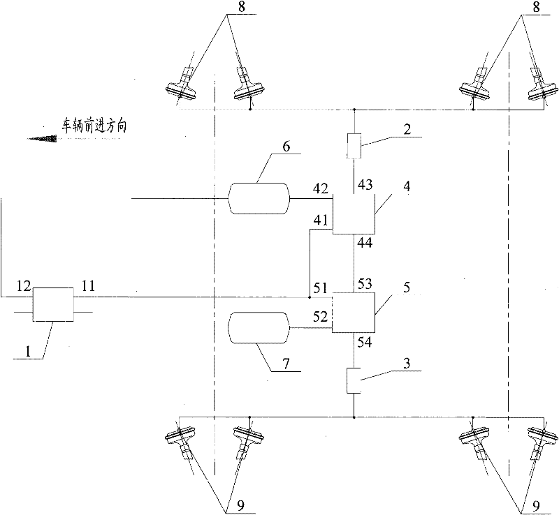
[0028] See figure 1 , which is a schematic diagram of the air brake unit in this embodiment.

[0029] The pneumatic brake unit mainly includes a foot brake valve 1, a first solenoid valve 2, a second solenoid valve 3, a first foot relay valve 4, a second foot relay valve 5, a first air storage tank 6 and a second storage tank. Inflator7.

[0030] Wherein, the air outlet 11 of the first chamber of the foot brake valve 1 communicates with the control air port 41 of the first foot relay valve 4 and the control air port of the second foot relay valve 5 respectively.

[0031] The first electromagnetic valve 2 is arranged betwe...


PUM


Abstract

The invention discloses an air pressure brake unit. A first solenoid valve is arranged between a plurality of right brake air chambers and a first air storage cylinder; a second solenoid valve is arranged between a plurality of left brake air chambers and a second air storage cylinder; an air outlet of a first chamber of a foot brake valve is communicated with control air ports of two foot relay valves; a first foot relay valve is arranged on an air path of the first solenoid valve and the first air storage cylinder; a second foot relay valve is arranged on an air path between the second solenoid valve and the second air storage cylinder; and brake efficiency of a vehicle can be guaranteed on the basis of reducing manufacturing cost of the vehicle. Preferably, an air outlet of the first foot relay valve is communicated with an air outlet of the second relay valve; and when any foot relay valve is failed, risky working conditions that the vehicle is out of control and unstable and the like can be effectively avoided or higher residual brake efficiency can be obtained. On the basis, the invention also provides a multi-shaft automobile chassis with the air pressure brake unit.

Description

technical field [0001] The invention relates to the technical field of engineering machinery, in particular to an air pressure braking unit and a multi-axle automobile chassis using the braking unit. Background technique [0002] The air pressure braking system of the existing vehicle uses a brake valve to control the communication between the high-pressure gas in the air storage tank and the brake air chamber, so as to realize air pressure braking according to the manipulation command. At the same time, in order to shorten the response time of the service brake and shorten the braking distance, a foot relay valve is generally installed on the pipeline between the foot brake valve and the brake air chamber, so that the compressed air in the air storage tank can quickly fill the brake air chamber. [0003] For multi-axle vehicles, most of the adjacent multi-axles (two or more axles) are in the form of penetrating balance, that is, multiple axles are controlled by a foot relay...

Claims


Application Information

Patent Timeline
Patent Type & Authority Applications(China)
IPC IPC(8): B60T13/26B60T13/68B60T15/04B60T15/18
Inventor 朱亚夫甘新廷曹永韩龙赵建国
Owner XUZHOU HEAVY MASCH CO LTD
Why Eureka
Try Eureka