Angle mechanically-operated controller with built-in rotary blade

A blade angle and adjuster technology, which is applied in the direction of mechanical equipment, machines/engines, non-variable pumps, etc., can solve the problem of the short distance of the drive shaft of the adjuster and the blade adjustment rod moving up and down, and the oil throwing of the adjuster , Planar bearings are easy to be damaged, etc., to shorten the rotation time and reduce mechanical wear

Inactive Publication Date: 2012-02-08
戴宏岸
View PDF5 Cites 12 Cited by
  • Summary
  • Abstract
  • Description
  • Claims
  • Application Information

AI Technical Summary

Problems solved by technology

When the main motor is working, although the regulator itself does not need to work (the angle of the pump blades is not adjusted), the plane bearing and transmission shaft in the regulator transmission seat have to rotate at high speed with the main motor shaft, causing the plane bearing to wear for a long time;
[0004] ② When the regulator is working, the plane bearing not only needs to rotate with the pump shaft at high speed, but also bears the axial adjustment pulling (push) force to adjust the angle of the water pump blade, which makes the plane bearing more easily damaged;
[0005] ③The self-weight load of the regulator is borne by the main motor casing. When the water pump starts to lift the shaft, the impact force on the pump axis is easy to damage the motor base bearing (thrust bearing) or the mirror plate of the main motor, and it is easy to damage the regulator plane bearing;
[0006] ④When the water pump and the main motor are working, the plane bearing and transmission shaft of the regulator need to rotate at a high speed with the main motor shaft, so the plane bearing runs at a high temperature for a long time, which will easily cause the lubricating oil to liquefy or even partially vaporize, resulting in prominent oil throwing phenomenon of the regulator ;
[0007] ⑤Although the main body of the hydraulic synchronous governor for the blade angle of the water turbine and water pump is installed and fixed on the top of the main motor shaft, the oil filling hole of the upper and lower oil cylinders and the inlet hole of the upper oil cylinder for supplying power to the small motor are not sealed tightly (the sealing material is not good enough), It also causes the regulator to throw oil prominently;
[0008] ⑥ The piston and the cylinder wall cannot be completely sealed, resulting in oil leakage from the upper cylinder to the lower cylinder;
[0009] ⑦ Blade angle locking performance is poor
[0010] ⑧The blade angle cannot be displayed remotely
In the past, the regulators for large pumps (water outlet diameter above 1600mm) all used mechanical display methods (install a scale plate on the blade adjustment rod, and install a pointer on the scale plate) to display the change of the pump blade angle, and it was impossible to leave the running unit to display the blade. Angle; especially for medium-sized water pumps (outlet diameter 700-1400mm), due to the small diameter of the runner, the distance that the drive shaft of the regulator and the blade adjustment rod move up and down is short, and it is impossible to clearly display the angle change of the pump blade with a mechanical display method. ;
[0011] ⑨Unable to fully adjust the pump blade angle
The current regulator (whether mechanical or hydraulic) can only adjust the angle of the pump blades manually or by clicking the button on the computer screen with the mouse according to the readings of the ammeter (or power meter) on the operating console of the pump station or the power distribution panel. The fully automatic adjustment of the pump blade angle seriously affects the efficiency of the fully-adjustable water pump

Method used


Image

  • Angle mechanically-operated controller with built-in rotary blade
  • Angle mechanically-operated controller with built-in rotary blade
  • Angle mechanically-operated controller with built-in rotary blade

Examples


Embodiment Construction

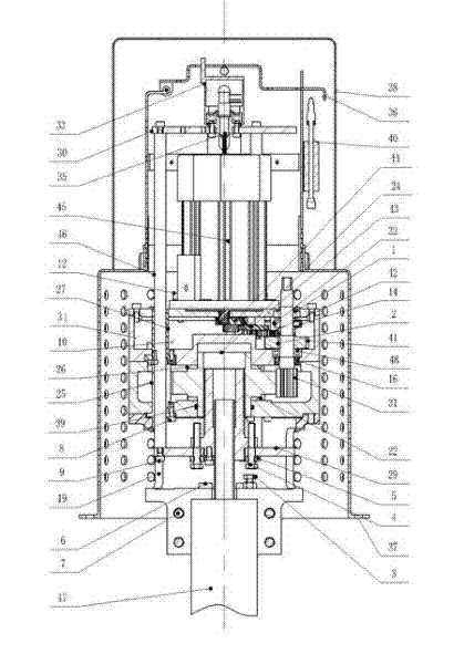
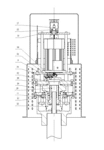
[0028] Referring to the accompanying drawings: A, install the oil-proof sleeve 27 on the upper box body 20, and press it with the hexagon socket head screw 8. Install the skeleton oil seal 16, the miniature bearing 48, and the four-axis 31;

[0029]B. Install a sealing ring 39 and a lower oil-proof sleeve 25 on the lower box body 18, press them with a hexagon socket head cap screw 8, install the lower pad 22, the large gear 24, and the upper pad 26. Install the content in A, press it with the inner hexagon screw 13, install the flat key 2, install the four-axis gear 41, install the bushing 32, press it with the set screw 14, install the single row deep groove ball bearing 1, install the miniature bearing 51, Install single row deep groove ball bearing 52, install three shafts 42, install two shafts 43, install one shaft 44, install miniature bearings 50, install balance weight 34, press with inner hexagonal screws 10, install cover 21, use inner hexagonal screws 9 Compress, in...


PUM


Abstract

The invention discloses an angle mechanically-operated controller with a built-in rotary blade, which comprises a rotating base, a box body and a programmable logic controller (PLC) and a digital display instrument. The angle mechanically-operated controller is characterized in that a regulator main body is fixed at the top end of a main motor shaft matched with a water pump and synchronously rotates with the rotation of the main motor shaft; an external housing is arranged and fixed at the top end of a main motor housing, a pump shaft and the main motor shaft are hollow shafts, the hollow shafts are internally respectively provided with a regulating pump pull (push) rod, a small motor is arranged on a regulator box body, an external power supply supplies electricity to the small motor through an appliance bracket arranged and fixed in the external housing and a power supply sliding ring; and the small motor automatically positively rotates or negatively through an appliance control system to drive a regulating pull rod in a transmission base to move up and down, so as to drive an blade of the water pump to rotate. The angle mechanically-operated controller can be used for converting displacement of the regulating pull rod into an angle variation of the blade, can also be used for automatically regulating the angle of the blade of the pump according to the change condition of water levels of inland and outland rivers and the load of the main motor, and is suitable for being used by all full-regulation water pump sets.

Description

technical field [0001] The invention relates to an adjusting device of an axial flow pump, in particular to a fully automatic adjuster for adjusting the angle of the pump vane and displaying the angle of the vane with numbers. Background technique [0002] There are two main types of regulators used in conjunction with existing domestic fully-regulated axial flow pumps (including guide vane mixed-flow pumps, the same below): one is an external fixed mechanical regulator; the other is a hydraulic turbine and water pump blade angle hydraulic regulator. synchronous governor. They have the following defects: [0003] ①The external fixed mechanical regulator is installed and fixed on the top of the main motor casing for the water pump. When the main motor is working, although the regulator itself does not need to work (the angle of the pump blades is not adjusted), the plane bearing and transmission shaft in the regulator transmission seat have to rotate at high speed with the ...

Claims


Application Information

Patent Timeline
Patent Type & Authority Applications(China)
IPC IPC(8): F04D15/00
Inventor 戴宏岸
Owner 戴宏岸
Why Eureka
Try Eureka