Optical connector and connector connection system

A technology of optical connectors and connectors, applied in the direction of instruments, optics, light guides, etc., can solve problems such as difficulty in reducing the distance between circuit boards and large connector thickness

Inactive Publication Date: 2012-02-08
FUJIKURA LTD
View PDF8 Cites 27 Cited by
  • Summary
  • Abstract
  • Description
  • Claims
  • Application Information

AI Technical Summary

Problems solved by technology

[0005] However, for example, an adapter is required to connect the above-mentioned MPO optical connector to a circuit board, and since the thickness of the connector (plug) itself is large, it is difficult to reduce the distance between circuit boards when a plurality of circuit boards are arranged side by side.

Method used


Image

  • Optical connector and connector connection system
  • Optical connector and connector connection system
  • Optical connector and connector connection system

Examples


Embodiment Construction

[0053] Hereinafter, an optical connector and a connector connection system according to Embodiment 1 of the present invention will be described with reference to the drawings.

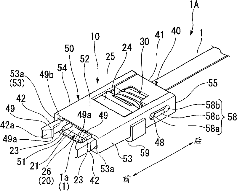
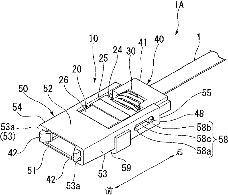
[0054] like Figure 1A , Figure 1B As shown, the above-mentioned optical connector 10 is mounted on the front end of the optical fiber 1 . Reference numeral 1A in the figure is assigned to the optical fiber with connector to which the optical connector 10 is attached to the tip of the optical fiber 1 .

[0055] like image 3 , Figure 4 As shown, the above-mentioned optical connector 10 is connected to the receiving-side optical connector 110 in a pushing manner by pressing against the receiving-side optical connector 110 (plug).

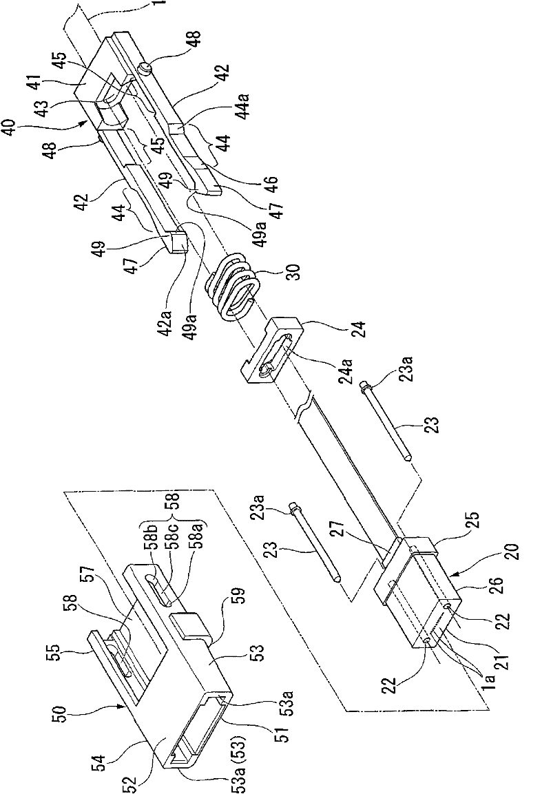
[0056] exist Figure 1A , Figure 1B , image 3 , Figure 4 , as shown by the arrow, for the optical connector 10, the engaging member 40 (refer to figure 2 ) The side where the front ends of the pair of elastic pieces 42 are located will be described as the front a...


PUM


Abstract

An optical connector includes: an engaging member having a pair of elastic pieces that can be engaged with locking portions on both sides of a receiving-side optical connector; and a movable tubular housing externally fitted to the engaging member, wherein the pair of elastic pieces approaches each other by an engagement with the locking portions on both sides of the receiving-side optical connector, and thereby, the housing becomes movable forward with respect to the portion of the engaging member that engages with the locking portions, and wherein an engagement state between the elastic pieces and the locking portions on both sides of the receiving-side optical connector is maintained as the pair of elastic pieces abuts an inside of the housing thereby regulating a movement in a direction of being separated from each other when the housing has moved forward with respect to the engaging member.

Description

[0001] This application claims the priority of Japanese Patent Application No. 2010-173056 filed in Japan on July 30, 2010 and Japanese Patent Application No. 2010-199954 filed in Japan on September 7, 2010, and uses the contents thereof here . technical field [0002] The present invention relates to an optical connector capable of being connected in a push-on manner and a connector connection system using the optical connector. Background technique [0003] As an optical connector, for example, an MPO type optical connector (F13 type optical connector specified in JIS C5982. MPO: Multi-fiber Push On) is known for connection of a plug-adapter-plug combination method. (For example, Japan Standards Association, "F1 3-shaped multi-core フアイバネクネクタ C 5982: 1997", JIS Handbook Electronic Test Method, Optoelectonics, ed.: Japan Standards Association, April 24, 1998). [0004] However, in recent years, a high-performance computer or computer system has mounted a plurality of photoe...

Claims


Application Information

Patent Timeline
Patent Type & Authority Applications(China)
IPC IPC(8): G02B6/38
CPCG02B6/3821G02B6/3885G02B6/3893G02B6/3897G02B6/4292G02B6/38875
Inventor 加藤诚司
Owner FUJIKURA LTD
Why Eureka
Try Eureka