Attitude control IP core based on PD control law and satellite attitude control moment calculation system using the same
A satellite attitude control and attitude control technology, applied in the field of aerospace electronics, can solve the problems of low reusability and unfavorable rapid design of aerospace electronic systems, etc., and achieve the effects of increased calculation speed, good reusability, and good design foundation
- Summary
- Abstract
- Description
- Claims
- Application Information
AI Technical Summary
Problems solved by technology
Method used
Image
Examples
specific Embodiment approach 1
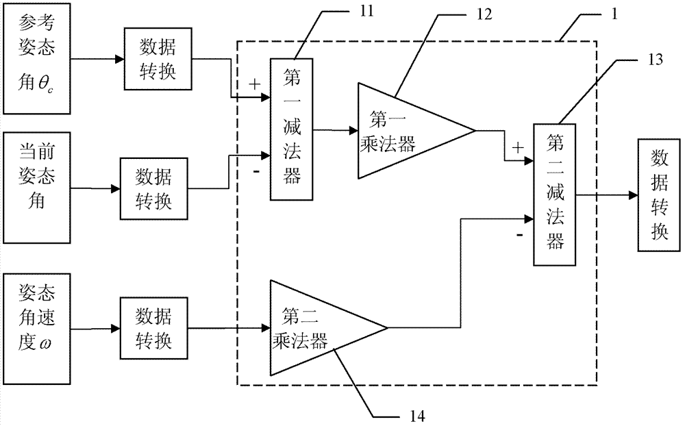
[0078] Specific implementation mode one, see figure 1 This embodiment will be described. A kind of attitude control IP core based on PD control law described in this embodiment comprises two subtractors and two multipliers, and this attitude control IP core adopts FPGA external input clock as calculation clock;
[0079] Among them, the reference attitude angle θ input by the positive input terminal of the first subtractor 11 c , the negative input terminal of the first subtractor 11 inputs the current attitude angle parameter, the output terminal output data of the first subtractor 11 is given to the first multiplier 12, and the first multiplier 12 is proportional to the data in the PD control algorithm Coefficient K P After multiplication, output product result data to the positive input end of the second subtractor 13;
[0080] The second multiplier 14 combines the input attitude angular velocity ω parameter with the differential coefficient K in the PD control algorithm ...
specific Embodiment approach 2
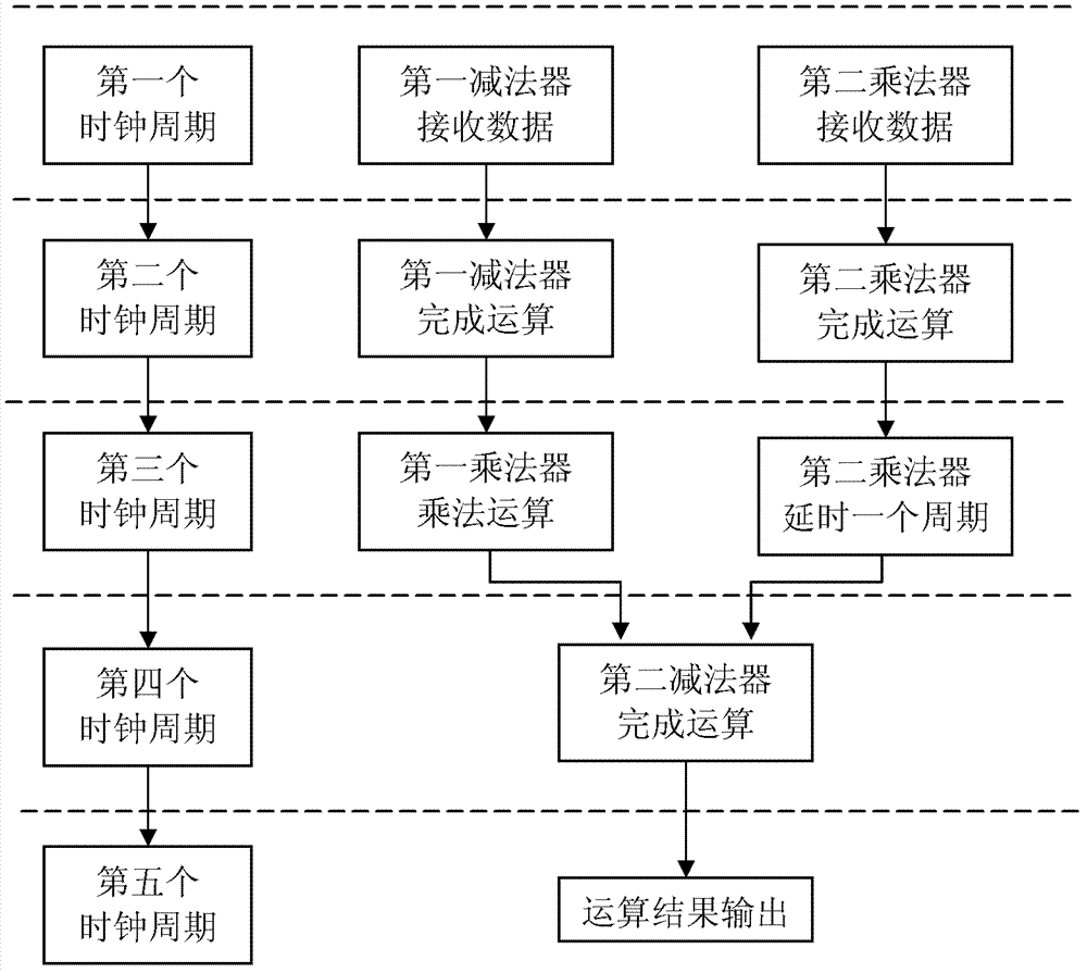
[0084] Specific Embodiment 2. Referring to FIG. 2, this embodiment will be described. This embodiment is a further description of the attitude control IP core based on the PD control law described in the first embodiment. Each calculation cycle of the attitude control IP core based on the PD control law in this embodiment is 5 clock cycles , the specific process is:
[0085] In the first clock cycle, the input reference attitude angle θ c Pass to the positive input end of the first subtractor 11, the current attitude angle passes to the negative input end of the first subtractor 11, and the attitude angular velocity ω passes to an input end of the second multiplier 14;
[0086] In the second clock cycle, the first subtractor 11 and the second multiplier 14 complete subtraction and multiplication respectively;
[0087] In the third clock cycle, the first multiplier 12 completes the multiplication operation, and the result of the second multiplier 14 is delayed by one cycle; ...
specific Embodiment approach 3
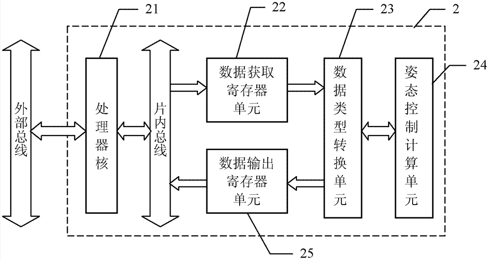
[0091] Specific implementation mode three, see image 3 To illustrate this embodiment, 2 in the figure is the satellite attitude control moment calculation system described in this embodiment. The satellite attitude control moment calculation system adopts the attitude control IP based on the PD control law described in the first or second embodiment. To achieve nuclear realization, the satellite attitude control moment calculation system described in this embodiment includes:
[0092] The processor core 21 is used to read the data required for calculating the attitude control moment through the external bus, and the data includes the reference attitude angle θ c , the current satellite attitude angle θ and angular velocity, and write the data into the data acquisition register; it is also used to read the attitude control torque data from the data output register through the on-chip bus and output it to the external data bus;
[0093] The data acquisition register unit 22 is...
PUM
 Abstract
Description
Claims
Application Information
 - R&D
- Intellectual Property
- Life Sciences
- Materials
- Tech Scout
- Unparalleled Data Quality
- Higher Quality Content
- 60% Fewer Hallucinations
Browse by: Latest US Patents, China's latest patents, Technical Efficacy Thesaurus, Application Domain, Technology Topic, Popular Technical Reports.
© 2025 PatSnap. All rights reserved.Legal|Privacy policy|Modern Slavery Act Transparency Statement|Sitemap|About US| Contact US: help@patsnap.com


