Method for making fine pattern on semiconductor device

A technology of fine patterns and production methods, applied in semiconductor/solid-state device manufacturing, electrical components, circuits, etc., can solve problems such as difficult to realize, low production efficiency, complex SADP technology, etc., to achieve accurate definition and improve production efficiency.

Active Publication Date: 2012-02-08
SEMICON MFG INT (SHANGHAI) CORP +1
View PDF3 Cites 21 Cited by
  • Summary
  • Abstract
  • Description
  • Claims
  • Application Information

AI Technical Summary

Problems solved by technology

[0009] Based on the above description, the existing SADP technology is relatively complicated, and the production efficiency is low when implemented
Moreover, after the anisotropic etching, the sidewall layer 103 needs to maintain a vertical and regular shape to define the line width of the fine pattern, which is difficult to achieve well for the anisotropic etching process.
Further, the sidewall layer 103 is deposited on the surface of the patterned sacrificial layer 102 and the surface of the exposed etching target layer 101. For smaller-sized fine patterns, the width of the exposed surface of the etching target layer 101 is very narrow, and the sidewall The thickness uniformity of layer 103 deposited on this position will be very poor, so it is difficult to etch to obtain the sidewall layer of ideal shape
Therefore, when the etched sidewall layer is used as a mask to etch the etching target layer 101, it is difficult to obtain a fine pattern of an ideal size.

Method used


Image

  • Method for making fine pattern on semiconductor device
  • Method for making fine pattern on semiconductor device
  • Method for making fine pattern on semiconductor device

Examples


Embodiment Construction

[0035] In order to make the object, technical solution, and advantages of the present invention clearer, the present invention will be further described in detail below with reference to the accompanying drawings and examples.

[0036] The present invention adopts simplified SADP technology to make the method flow diagram of fine pattern as figure 2 As shown, it includes the following steps, which are combined below Figure 2a to Figure 2e Be explained.

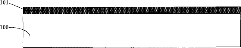
[0037] Step 21, see Figure 2a , deposit an etching target layer 201 on the semiconductor substrate 200 .

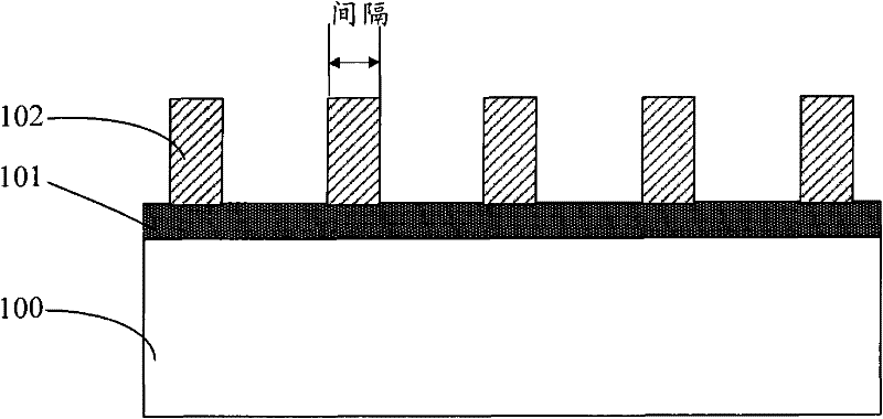
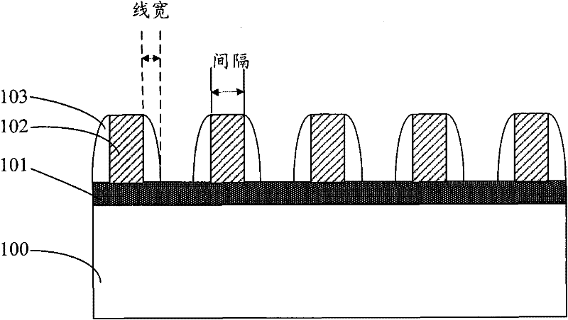
[0038] Step 22, see Figure 2b , sequentially depositing an organic layer 202, a first hard mask layer 203, and coating a photoresist layer (not shown in the figure) on the surface of the etching target layer 201, and exposing, developing and patterning the photoresist layer, patterning The gaps between the photoresist layers are used to define intervals of fine patterns; using the patterned photoresist layer as a ...


PUM


Abstract

The invention provides a method for making a fine pattern on a semiconductor device. The fine pattern comprises gaps and lines which are alternated with one another. In the method, hardened side wall layers are formed by adopting a mode of performing ion injection on two sides of an organic layer; a non-injected organic layer between the hardened side wall layers is removed by ashing; the widths of the hardened side wall layers are the widths of the lines of the fine pattern; and gaps between the hardened side wall layers are the gaps of the fine pattern. By the manufacturing method, a self-alignment double-pattern technology is simplified greatly under the condition of guaranteeing the accuracy of the fine pattern.

Description

technical field [0001] The invention relates to the technical field of semiconductor manufacturing, in particular to a method for manufacturing fine patterns of semiconductor devices. Background technique [0002] At present, for fine patterns formed by alternately arranged lines (lines) and spaces (spaces) on a substrate, self-aligned double patterning (SADP, Self-Aligned Double Patterning) technology is generally used. [0003] The existing method for forming a fine pattern using SADP technology includes the following steps, combined below Figure 1a to Figure 1e Be explained. [0004] Step 11, see Figure 1a , deposit an etching target layer 101 on the semiconductor substrate 100 . [0005] Step 12, see Figure 1b On the surface of the etching target layer 101, a sacrificial layer 102 is sequentially deposited, a photoresist layer (not shown in the figure) is coated, and the photoresist layer is patterned by exposure and development. The width of the patterned photores...

Claims


Application Information

Patent Timeline
Patent Type & Authority Applications(China)
IPC IPC(8): H01L21/027H01L21/311
Inventor 何其旸张翼英
Owner SEMICON MFG INT (SHANGHAI) CORP
Why Eureka
Try Eureka