Printed circuit board

A technology for printed circuit boards and power supplies, which is applied to printed circuit parts, printed circuits connected with non-printed electrical components, etc., and can solve the problem of increasing the pin resistance value of the plug-in

Inactive Publication Date: 2012-02-08
HONG FU JIN PRECISION IND (SHENZHEN) CO LTD +1
View PDF6 Cites 2 Cited by
  • Summary
  • Abstract
  • Description
  • Claims
  • Application Information

AI Technical Summary

Problems solved by technology

However, this structure is not very effective in preventing cold welding, and m

Method used


Image

  • Printed circuit board
  • Printed circuit board
  • Printed circuit board

Examples


Embodiment Construction

[0015] Below in conjunction with accompanying drawing and preferred embodiment the present invention is described in further detail:

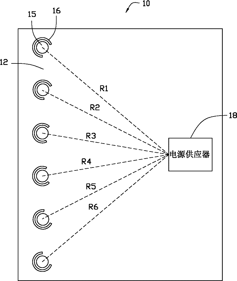
[0016] see figure 2 , the preferred embodiment of the printed circuit board of the present invention includes a power layer 10 and a power supply 18 . The power supply layer 10 is provided with a layer of copper foil 12 , an insertion hole 15 , and a thermal relief 16 . In this embodiment, assuming that the power supply 18 is disposed on the top layer of the entire printed circuit board, the power supply 18 is disposed on the power layer 10 . In other embodiments, the power supply 18 is generally disposed on the top layer or the bottom layer of the entire printed circuit board, and is connected to the power layer 10 and the ground layer through other via holes.

[0017] The copper foil 12 is laid on the surface of the power layer 10 . The plug-in hole 15 runs through the entire printed circuit board, and is used to make the pins of the comp...


PUM


Abstract

The invention provides a printed circuit board. A copper foil, an insert hole and an anti-thermal relief groove are arranged on one layer of the printed circuit board, wherein the copper foil is paved on the surface of the layer; the insert hole runs through the whole printed circuit board; and the anti-thermal relief groove is formed on the surface of the layer and not covered by the copper foil, surrounds the insert hole and comprises an opening fading a power supply positioned on the printed circuit board. By the printed circuit board, not only the condition of insert hole cold-welding caused by over-high thermal relief speed can be avoided, but also a resistance value between a pin of an insert and the power supply is relatively lower.

Description

technical field [0001] The invention relates to a printed circuit board. Background technique [0002] In order to have a lower impedance, the power layer and ground layer of the printed circuit board are generally laid with a large area of ​​copper foil. In this way, when the plug-in connected to the power layer and the ground layer is heated by the tin furnace, if the pins of the plug-in are not properly thermally isolated, the heat will be quickly taken away by the large-area copper foil on the power layer and the ground layer. As a result, the through-holes of the power layer and the ground layer have a low rate of tin intake, resulting in cold welding, that is, it is not easy to solder the plug-in. Such as figure 1 As shown, four anti-radiation grooves 2 are generally arranged around the through hole 1, and the four anti-radiation grooves 2 reduce the heat dissipation area of ​​the copper foil 3 around the plug-in hole (that is, the through hole 1), slowing down the p...

Claims


Application Information

Patent Timeline
IPC IPC(8): H05K1/02H05K1/18
Inventor 赖盈佐白育彰
Owner HONG FU JIN PRECISION IND (SHENZHEN) CO LTD
Why Eureka
Try Eureka