Optimizing apparatus

An optimization device, carbon dioxide technology, applied in the direction of rolling mill control devices, metal rolling, manufacturing tools, etc., can solve the problem of large energy consumption, to achieve the effect of ensuring product quality and control optimization

Active Publication Date: 2012-02-08
TOSHIBA MITSUBISHI-ELECTRIC IND SYST CORP
View PDF7 Cites 11 Cited by
  • Summary
  • Abstract
  • Description
  • Claims
  • Application Information

AI Technical Summary

Problems solved by technology

[0004] In this way, since the thin plate hot rolling equipment transmits the rolled material, it ...

Method used


Image

  • Optimizing apparatus
  • Optimizing apparatus
  • Optimizing apparatus

Examples


Embodiment approach 1

[0037] >

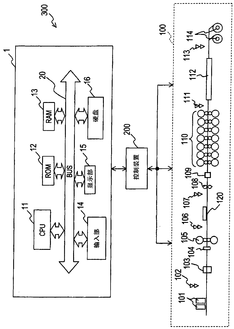
[0038] figure 1 It is a configuration diagram showing the configuration of a hot rolling system to which the optimization device according to Embodiment 1 of the present invention is applied.

[0039] Such as figure 1 As shown, the hot rolling system 300 includes the optimization device 1 related to Embodiment 1, the hot rolling device 100 for rolling the rolling material in a heated state, and the control device 200 for controlling the hot rolling device 100. The optimization device 1 is connected to the control device 200.

[0040] The hot rolling apparatus 100 includes a slab heating furnace 101 for heating a rolled material 120 by burning fossil fuels such as diesel or natural gas, a slab heating furnace outlet thermometer 102 for measuring the outlet temperature of the slab heating furnace 101, A high-pressure descaling unit 103 that sprays high-pressure water above and below the rolled material 120 to remove iron and phosphorus (scale) from the surface of t...

Embodiment approach 2

[0122] Next, an optimization device 1A according to Embodiment 2 of the present invention will be described.

[0123] The optimization device 1A according to Embodiment 2 and figure 1 The optimization device 1 according to the first embodiment shown is the same, and is connected to the control device 200 that controls the hot rolling device 100 .

[0124] Furthermore, optimization device 1A according to Embodiment 2 includes CPU 11A, ROM 12 , RAM 13 , input unit 14 , display unit 15 , and hard disk 16 . However, since the ROM 12 , RAM 13 , display unit 15 , and hard disk 16 are the same as those included in the optimization device 1 according to Embodiment 1, the configurations denoted by the same reference numerals will be omitted here.

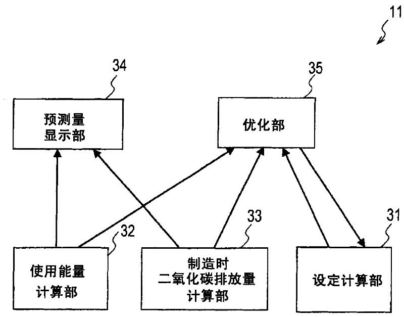
[0125] Figure 6 It is a configuration diagram showing the configuration of CPU 11A included in optimization device 1A according to Embodiment 2 of the present invention.

[0126] Such as Figure 6 As shown, the CPU 11 functionally inclu...

Embodiment approach 3

[0132] Next, an optimization device 1B according to Embodiment 3 of the present invention will be described.

[0133] The optimization device 1B related to Embodiment 3 and figure 1 The optimization device 1 according to the first embodiment shown is the same, and is connected to the control device 200 that controls the hot rolling device 100 .

[0134] Furthermore, optimization device 1B according to Embodiment 3 of the present invention includes CPU 11B, ROM 12 , RAM 13 , input unit 14 , display unit 15 , and hard disk 16 . However, since the ROM 12 , RAM 13 , input unit 14 , display unit 15 , and hard disk 16 are the same as those included in the optimization device 1 according to the first embodiment, the description thereof will be omitted.

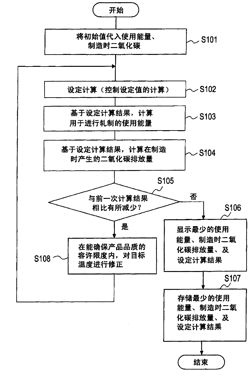
[0135] Figure 7 It is a configuration diagram showing the configuration of the CPU 11B included in the optimization device 1B according to Embodiment 3 of the present invention.

[0136] Such as Figure 7 As shown, the CPU 11B f...


PUM

PropertyMeasurementUnit
Tensile strengthaaaaaaaaaa

Abstract

Provided an optimizing apparatus comprising a setting calculation unit (31) for calculating a control setting value for a hot rolling apparatus (100) to roll a rolling material (120), on the basis of the initial sizes, the initial temperature and the target temperature of the rolling material (120), a working energy calculation unit (32) for calculating a working energy necessary for the hot rolling apparatus (100) to roll the rolling material (120), on the basis of the control setting value, a during-manufacture carbon dioxide discharge calculating unit (33) for calculating the quantity of carbon dioxide to be discharged in the hot rolling apparatus (100), on the basis of the working energy and the carbon dioxide discharge coefficient, and an optimizing unit (35); for calculating the target temperature both as the temperature at or higher than the value necessary for retaining the quality of the rolling material (120) to be rolled, and as a temperature for minimizing at least one of the working energy or the carbon dioxide discharge.

Description

technical field [0001] The invention relates to an optimization device for optimizing the control of rolling equipment, thereby ensuring the product quality of the rolled material when rolling the rolled material in the rolling equipment, and reducing the energy used and the carbon dioxide emitted At least one of the quantities is the smallest. Background technique [0002] Rolling facilities for rolling metal materials include thin plate hot rolling facilities, thick plate rolling facilities, cold rolling facilities for producing steel plates (hereinafter referred to as steel plates), steel section steel rolling facilities, bar steel and wire rods Rolling equipment, as well as aluminum and copper rolling equipment. [0003] For example, a hot thin plate rolling facility heats a cuboid steel material called a slab to about 1200° C. with a slab heating furnace 101 and rough-rolls it with a roughing mill to obtain a strip with a thickness of about 30 to 40 mm. At this time, ...

Claims


Application Information

Patent Timeline
IPC IPC(8): B21B37/00
CPCB21B37/74B21B37/00
Inventor 今成宏幸北乡和寿
Owner TOSHIBA MITSUBISHI-ELECTRIC IND SYST CORP
Why Eureka
Try Eureka