Eureka AIR delivers breakthrough ideas for toughest innovation challenges, trusted by R&D personnel around the world.

Sheet welding method

A welding method and sheet metal technology, which is applied in the field of sheet metal welding, can solve the problems of low welding efficiency of single gun and single wire, low welding efficiency, and large deformation of large-size sheet metal, so as to reduce the workload of post-weld adjustment and improve Production efficiency, the effect of uniform deformation

Active Publication Date: 2012-02-15
CRRC TANGSHAN CO LTD
View PDF2 Cites 8 Cited by
  • Summary
  • Abstract
  • Description
  • Claims
  • Application Information

AI Technical Summary

Problems solved by technology

[0004] When welding large-size profiles in the prior art, the efficiency of single-gun single-wire welding is low, and welding is performed along each butt joint groove in turn. After welding, the large-size sheet metal is deformed and the workload of adjustment and repair is large.
[0005] Although the single-gun double-wire welding is fast, a single gun can only weld one seam at a time, so the welding efficiency is low, and the deformation of the large-size sheet after welding is also large, and the workload of adjustment and repair is large.
[0006] It can be seen that the sheet metal welding method in the prior art, whether it is single-gun single-wire welding or single-gun double-wire welding, because the weld seam is very long, the stress generated between the sheets during welding cannot be effectively balanced, and local Deformation, due to the accumulation of deformation, the larger the deformation of the weld on both sides, it seriously affects the flatness or contour of the sheet after welding, the workload of adjustment and repair is large, and the production efficiency is low
[0007] Moreover, due to the use of single-gun single-wire welding or single-gun double-wire welding, each weld seam is welded sequentially, and the welding efficiency is low

Method used


Image

  • Sheet welding method
  • Sheet welding method
  • Sheet welding method

Examples


Embodiment Construction

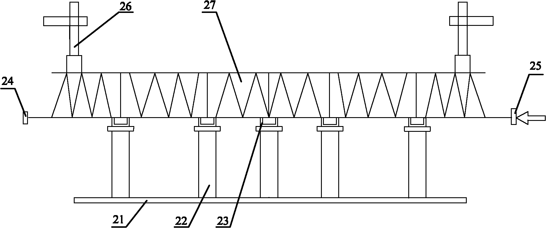
[0022] In order to make the purpose, technical solutions and advantages of the present invention clearer, the technical solutions in the embodiments of the present invention will be clearly and completely described below in conjunction with the accompanying drawings in the embodiments of the present invention. Obviously, the described embodiments are the Some, but not all, embodiments are invented. Based on the embodiments of the present invention, all other embodiments obtained by persons of ordinary skill in the art without making creative efforts belong to the protection scope of the present invention.

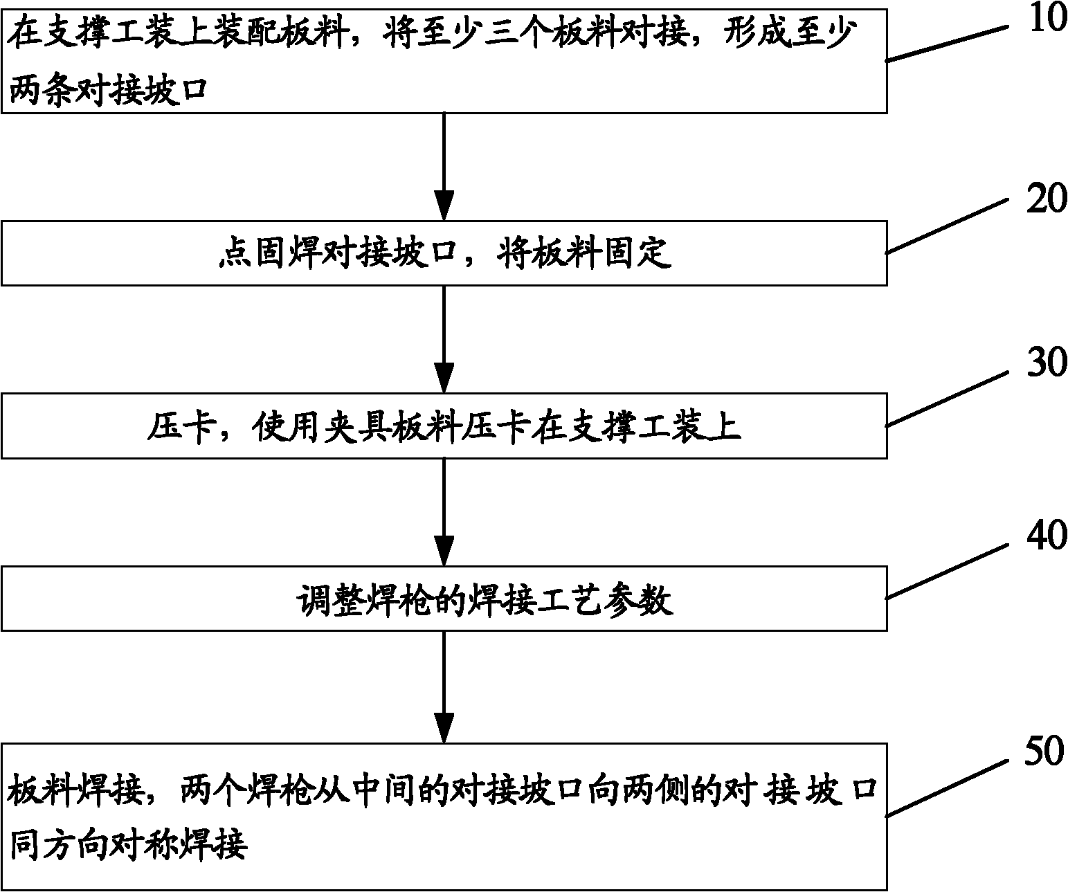
[0023] refer to figure 1 , figure 1 It is a schematic flow chart of the plate welding method provided by the first embodiment of the present invention.

[0024] In the first embodiment of the present invention, the sheet metal welding method includes:

[0025] Step 10, assembling panels on the supporting tool, butting at least three panels to form at least two butt joint...


PUM

PropertyMeasurementUnit
lengthaaaaaaaaaa

Abstract

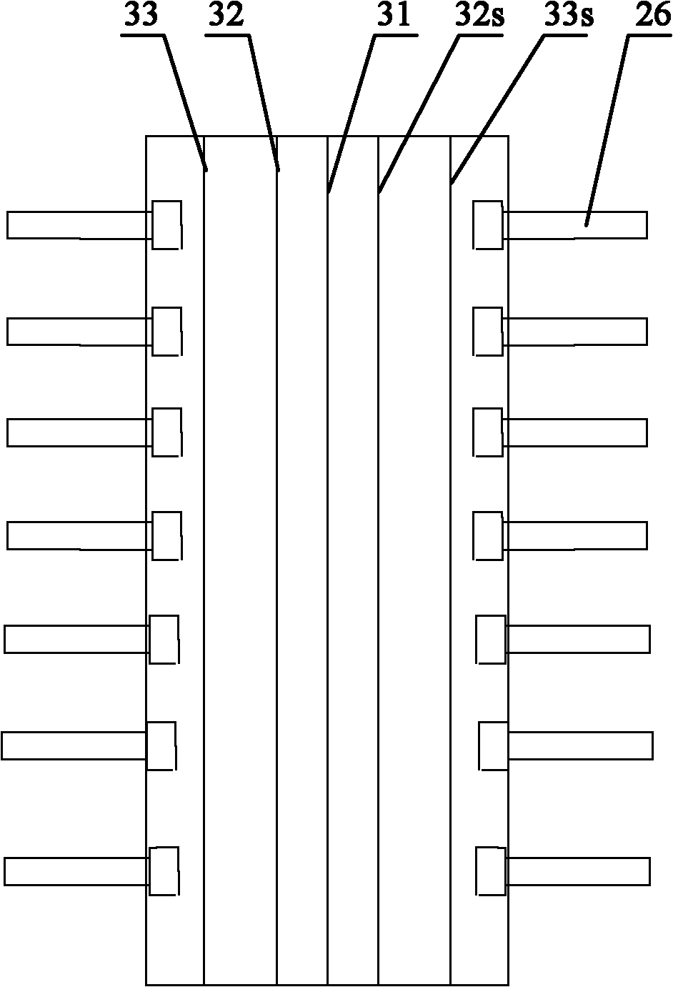
The invention discloses a sheet welding method which comprises the following steps of: assembling sheets on a support device, wherein at least three sheets are in butt joint to form at least two butt-joint grooves; tack-welding the butt-joint grooves, and fixing the sheets; pressing and clamping the sheets on the support device with a fixture; adjusting the welding technological parameters of a welding gun; and welding the sheets, wherein two welding guns perform equidirectional symmetric welding from the middle butt-joint groove towards the butt-joint grooves on the two sides. In the invention, two welding guns are adopted to perform equidirectional symmetric welding from the middle butt-joint groove towards the butt-joint grooves on the two sides. Through the invention, the stress produced by the sheets during the welding can be effectively balanced, and the heat can be quickly dispersed so that the deformation of the welded sheets is more uniform, the deformation generated by the welding of large-size sheets can be reduced, the regulation and maintenance workload after welding is reduced, and the production efficiency is improved.

Description

technical field [0001] The invention relates to welding technology, in particular to a plate welding method. Background technique [0002] Sheets include flat sheets or curved sheets, flat sheets include flat sheets and flat profiles, and curved sheets include curved sheets and curved profiles. In engineering applications, it is necessary to weld multiple flat or curved panels into large-sized panels, which are used as outer skin materials for trains, ships or aircraft. [0003] In the prior art, the welding method of large-sized sheet metal is to assemble multiple sheets butt joints to form a butt groove, and use one welding torch and one welding wire for welding (single-gun single-wire welding), or use one welding torch and two welding wires. Root welding wire (single gun double wire welding). [0004] When welding large-size profiles in the prior art, the efficiency of single-gun single-wire welding is low, and welding is performed along each butt joint groove in turn. ...

Claims


Application Information

Patent Timeline
Patent Type & Authority Applications(China)
IPC IPC(8): B23K9/00B23K33/00B23K37/04
Inventor 刘春宁唐衡郴胡文浩尹德猛王陆钊
Owner CRRC TANGSHAN CO LTD
Why Eureka
Eureka Blog
Learn More