
Ground wind generating set for high air power generation

A generator set and generator technology, applied in the direction of wind motor combination, wind engine, installation/supporting wind engine configuration, etc., can solve the problems of wasting wind resources, low power generation efficiency, and increased weight of airbags, so as to increase power generation, The effect of high wind speed

Inactive Publication Date: 2012-02-15
青岛华创风能有限公司
View PDF6 Cites 4 Cited by
  • Summary
  • Abstract
  • Description
  • Claims
  • Application Information

AI Technical Summary

Problems solved by technology

The current utilization of wind energy is limited to the low altitude of tens of meters to hundreds of meters
However, at altitudes ranging from a few kilometers to 10,000 meters, not only the wind speed is greater, but also the wind force is stable. The time of no wind blowing is less than 5% of the year.
The problem with this structure is that the transmission chain is designed on the airbag, which will undoubtedly increase the weight of the airbag and increase the safety hazard in the air. Moreover, the power generation efficiency of this structure is relatively low, which cannot meet the requirements of power generation, and not only wastes a lot of wind power resources, but also wasteful from an economic profit point of view

Method used


Image

  • Ground wind generating set for high air power generation
  • Ground wind generating set for high air power generation
  • Ground wind generating set for high air power generation

Examples


Embodiment

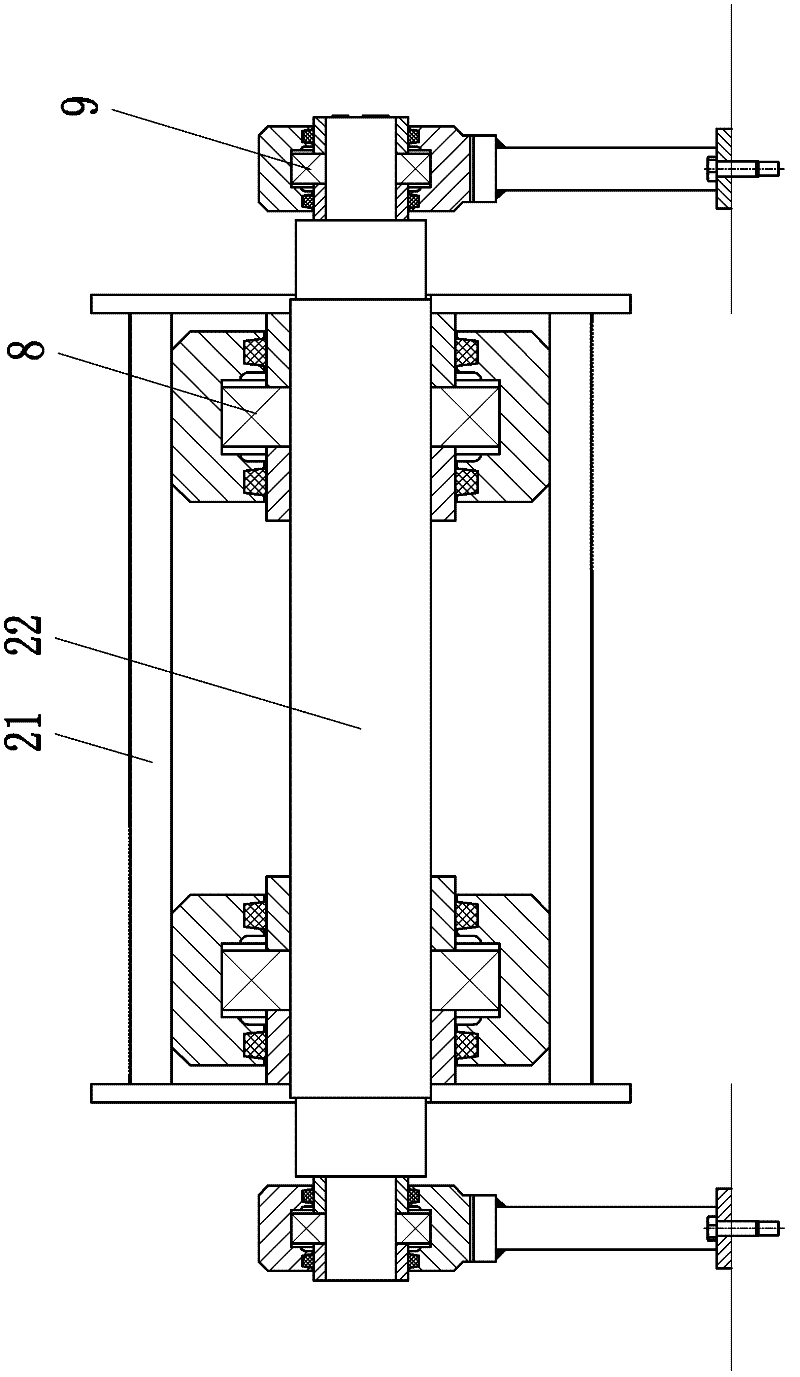
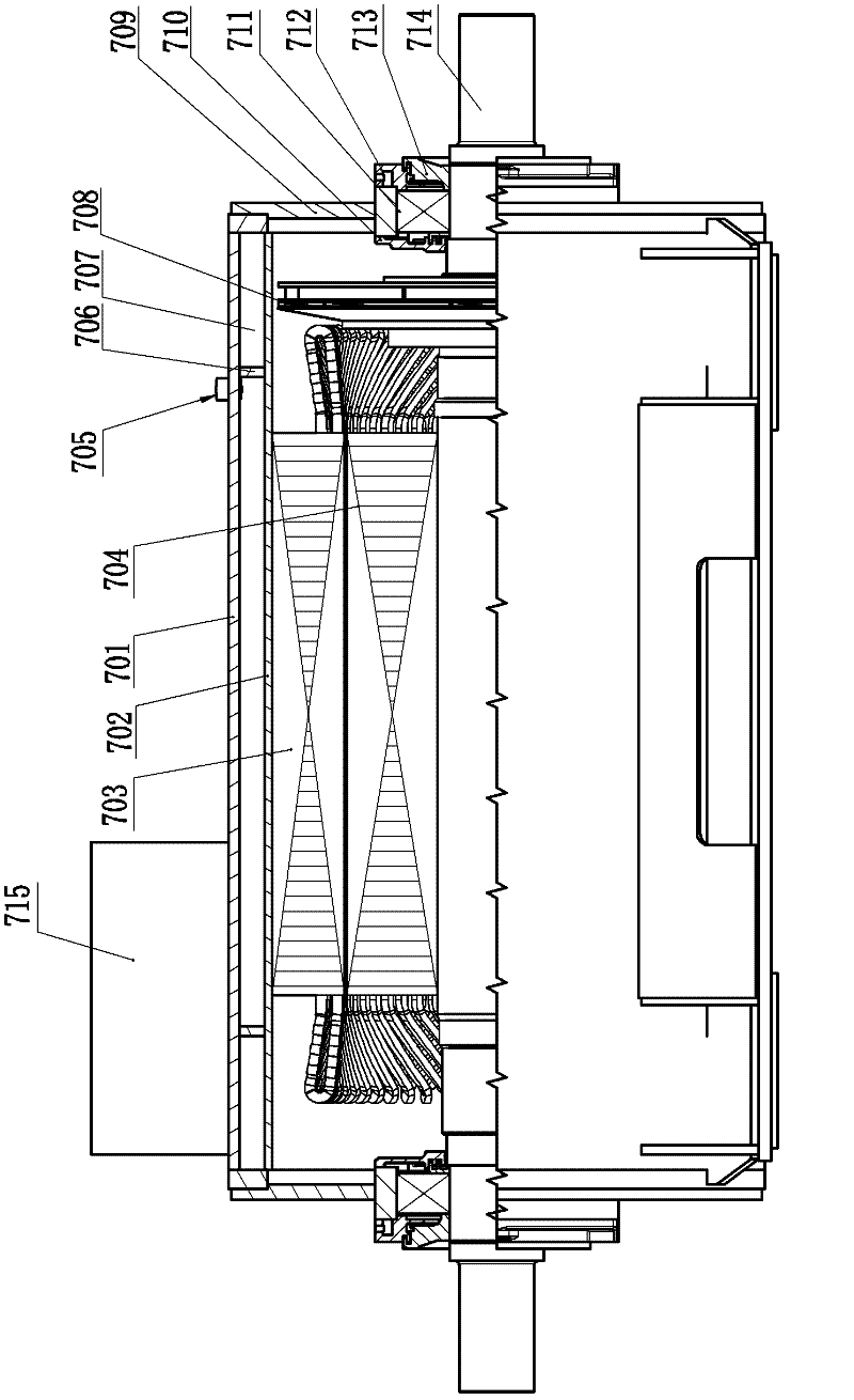
[0020] Example: such as figure 1 As shown, the present invention includes a generator 1 and shaft couplings 6, 6' symmetrically arranged on both sides of the generator 1, gearboxes 5, 5', brakes, rollers 2, 2', clutches 4, 4' and motors 1, 1', the two ends of the rotor shaft 714 of the generator 7 are respectively connected with a speed-up box through the coupling 6, 6', and the two ends of the drum 4, 4' are respectively connected with a brake, and the speed-up box 5, 5' and the brakes 31, 32 at one end of the drum 2, 2' are connected respectively, and the brakes 33, 34 at the other end of the drum 2, 2' are connected with the motors 1, 1' respectively through the clutches 4, 4'. When the generator 7 generates electricity, The two drums 2, 2' are respectively connected to the aerial working umbrella through cables, and the two clutches 4, 4' are respectively connected to the external control part, and the two clutches 4, 4' work alternately through the external control, so as...


PUM


Abstract

The invention discloses a ground wind generating set for high air power generation, and belongs to the technical field of high air wind power generation. The ground wind generating set comprises a generator, and couplers, speed increasing boxes, brakes, rollers, clutches and motors, which are symmetrically arranged on two sides of the generator; two ends of a rotor shaft of the generator are connected with the speed increasing boxes through the couplers; two ends of the rollers are connected with the brakes; the speed increasing boxes are connected with a brake at one end of the roller; the brake at the other end of the roller is connected with the motors through the clutches; and when the generator generates power, the two rollers are connected with a midair work doing umbrella through mooring ropes, and the two clutches are connected with an external control part and are controlled to alternately work, so that the generator continuously generates power and the power generation of the generator is improved. The ground wind generating set can transfer midair mechanical energy to the ground; and a rotating speed transmitted by the rollers is improved by the speed increasing boxes, so that a rotating speed at one end of an output shaft reaches a rated rotating speed required by the generator.

Description

technical field [0001] The invention belongs to the technical field of high-altitude wind power generation, in particular to a high-altitude ground wind power generating set that is easier to convert wind energy into electric energy. Background technique [0002] my country is a country with large wind energy resources, but few people have noticed that our country is also a country with high-altitude wind energy. Current wind energy utilization is limited to the low altitude of tens of meters to hundreds of meters. However, at altitudes ranging from a few thousand meters to 10,000 meters, not only the wind speed is stronger, but also the wind force is stable. Less than 5% of the year's time without wind blows. Experts generally believe that high-altitude wind energy is hundreds of times more than ground wind energy, and construction of aerial wind power plants can be considered. It is understood that at present, the wind density of the most advanced ground wind power stati...

Claims


Application Information

Patent Timeline
Patent Type & Authority Applications(China)
IPC IPC(8): F03D9/00H02K7/10H02K5/20F03D9/25F03D13/20
CPCY02E10/72Y02E10/728
Inventor 王冠一
Owner 青岛华创风能有限公司
Learn More