Mechanical clock mechanism and design method thereof

A technology of mechanical clocks, design methods, applied in mechanically driven clocks, movement size, clocks, etc.

Inactive Publication Date: 2012-02-15
烟台北极星股份有限公司
View PDF5 Cites 4 Cited by
  • Summary
  • Abstract
  • Description
  • Claims
  • Application Information

AI Technical Summary

Problems solved by technology

Even so, it has not been able to solve the design problem of the coaxial structure of the hour, minute, and second hands of the mechanical clock movement, especially after the tourbillon mechanism is i

Method used


Image

  • Mechanical clock mechanism and design method thereof
  • Mechanical clock mechanism and design method thereof
  • Mechanical clock mechanism and design method thereof

Examples


Embodiment 1

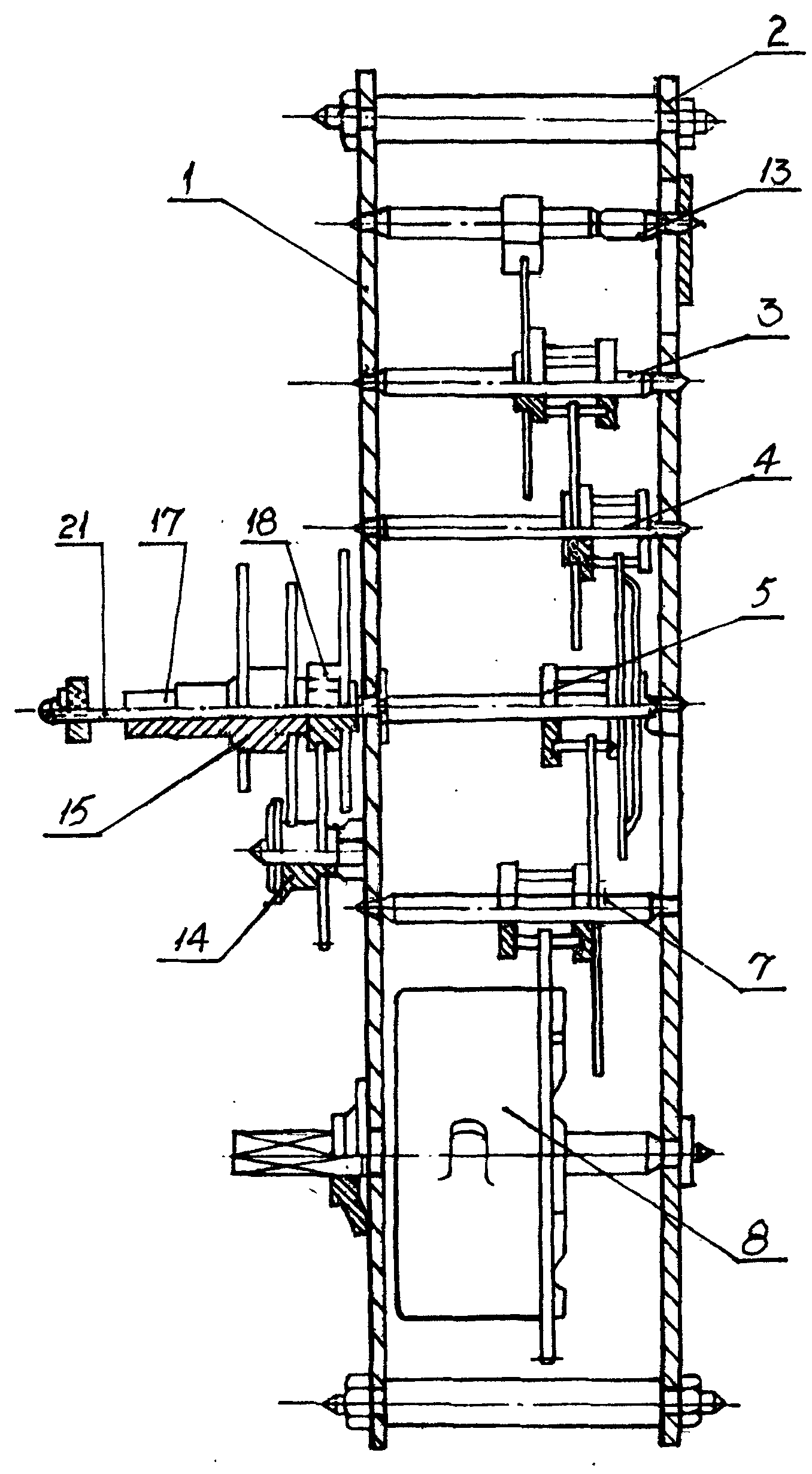
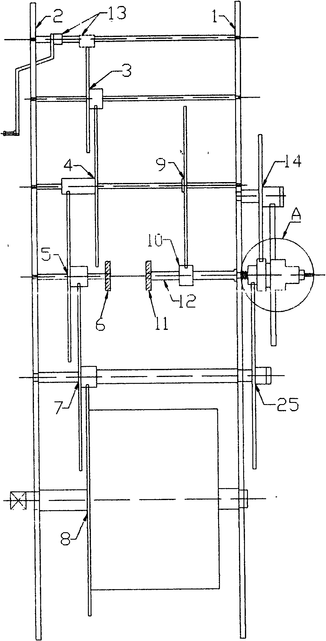
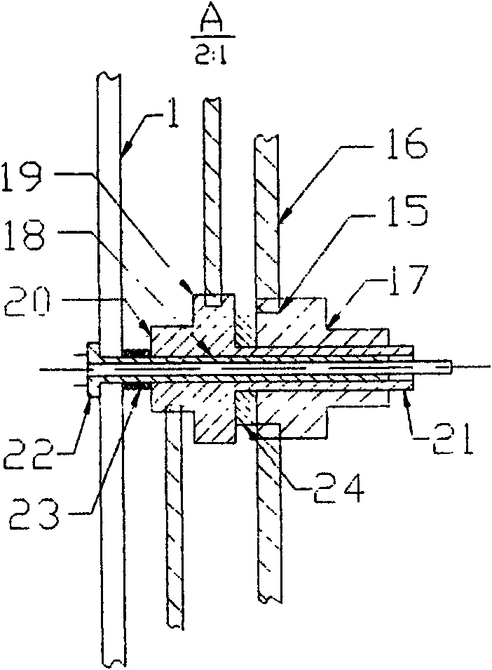
[0033] A design method for a mechanical clock movement according to Embodiment 1 of the present invention, which includes an ordinary three-needle mechanical clock used by ordinary consumers as the design object, and is adopted to meet the national standard GB / T 22772- "Mechanical Pendulum Clock" The technical index of 2008 is the premise, and the mechanical power mechanism of the clock movement is based on the spring-type power source. The mechanical desk clock and mechanical wall clock with a winding cycle of 31 days provide an improved design of the hour, minute, and second three-hand coaxial The overall design scheme of the mechanical clock movement with heart structure. On this basis, taking the existing mechanical clock movement as the prior art, its structure is: the front splint, the rear splint and the splint column between the two splints together constitute the support frame of the mechanical clock movement described in Embodiment 1 , the head wheel assembly include...

Embodiment 2

[0038] The design method of a mechanical clock movement described in Embodiment 2 of the present invention includes the design requirements of seat-type high-end three-needle mechanical clocks used by high-end consumers, so as to meet the national standard "Mechanical Pendulum Clock" GB / The technical index of T 22772-2008 is the premise, and the clockwork power source is used as the mechanical power mechanism of the clock movement. The mechanical seat type high-end see-through clock with a winding cycle of 31 days provides hours, minutes and seconds with improved design. The overall design scheme of a mechanical clock movement with a three-needle concentric structure. On this basis, taking the existing mechanical clock movement as the prior art, its structure is: the front splint, the rear splint and the splint column between the two splints together constitute the support frame of the mechanical clock movement described in Embodiment 2 The head wheel assembly includes a whee...

Embodiment 3

[0043] A design method of a mechanical clock movement in Embodiment 3 of the present invention, which includes meeting the design requirements of high-end three-needle mechanical clocks used by high-end consumers, so as to meet the national standard GB / T 22772-2008 of "Mechanical Pendulum Clock" The technical index is the premise, and the power source of the uniform wheel is used as the mechanical power mechanism of the clock movement. The mechanical stand-type high-end see-through clock with a winding cycle of 14 days provides the improved design of the hour, minute and second three needles at the same time. The overall design scheme of the mechanical clock movement with the axis structure. On this basis, with existing mechanical clock movement (see figure 1 ) is the prior art, its structure is: the splint column between the front splint, the rear splint and the two splints together constitute the support frame of the mechanical clock movement described in the present embodim...


PUM


Abstract

The invention discloses a mechanical clock mechanism and a design method thereof and relates to the technical field of time-measuring instruments. The invention has the technical scheme that the design method of the mechanical clock mechanism comprises the selection of mechanical energy motive force and the design of a power driving mechanism and is characterized by comprising the following stepsof: adopting the half-axle structure design for a three-wheel assembly; arranging a small splint support at the axle end part of the half-axle structure and enabling a center hole of a front splint of the small splint support to mark out a space for mounting a second pinion assembly; fixedly arranging a second pinion tube in the center hole of the front splint; sleeving a time-travel driving mechanism outside the second pinion tube; and arranging the second pinion assembly and movably mounting the second pinion in the second pinion tube, wherein second pinion teeth are in meshed connection with four secondary pinion pieces on a four-wheel assembly and form a second hand, minute hand and hour hand coaxial mounting structure together with a minute hand tube and a hour hand tube. Compared with the prior art, the mechanical clock mechanism and the design method thereof disclosed by the invention have the outstanding substantive characteristics and remarkable progress of novel design and conception, distinct and simple structure, second hand, minute hand and hour hand coaxial mounting, improved aesthetic feeling and kinetic feeling, improved added value of products and increased economic benefit of enterprises.

Description

technical field [0001] The invention relates to the technical field of timing instruments, in particular to a design method of a three-needle mechanical clock movement with a second hand and a coaxial structure with the hour and minute hands and the technical field of the movement. Background technique [0002] In the existing mechanical clock product market, the most common design method is the mechanical clock produced and processed according to the national standard "Mechanical Pendulum Clock" GB / T22772-2008, which includes desk clocks, wall clocks, and grandfather clocks; their common characteristics are : There are only minute and hour hands in the center of the clock dial, and there is no second hand. The pendulum swings reciprocatingly under the drive of the escapement mechanism. At the same time, the timing accuracy of the clock is controlled by adjusting the length of the pendulum. The power drive mechanism for travel time drive and timekeeping drive They are indepe...

Claims


Application Information

Patent Timeline
IPC IPC(8): G04B33/00G04B1/00
Inventor 张兆基于洪运姜巧林林强杜恒彦姬永刚刘静邵明霞
Owner 烟台北极星股份有限公司
Why Eureka
Try Eureka