Radius compensation algorithm for convex contour closed-angle linear and circular arc composite transitional cutting tool

A tool radius and convex profile technology, applied in computer control, instruments, simulators, etc., can solve problems such as long dwell time, sharp corner burns, difficulty in increasing processing speed, etc., achieve smooth and continuous tool center trajectory, and solve sharp corner burns Effect

Inactive Publication Date: 2012-02-15
DALIAN JIAOTONG UNIVERSITY
View PDF5 Cites 22 Cited by
  • Summary
  • Abstract
  • Description
  • Claims
  • Application Information

AI Technical Summary

Problems solved by technology

[0004] In order to solve the above-mentioned problems in the prior art, the present invention proposes a method that fully combines the advantages of the B-type tool radius compensation method and the C-type tool radius compensation method, which can solve the problem that the B-type tool radius compensation method stays too long at sharp corners. The tool radius compensation algorithm for convex contour sharp corner straight line circular arc composite transition can avoid the problem of frequent acceleration and deceleration caused by the broken line transition caused by the C-type tool radius compensation method, which can cause sharp corner burns and make it difficult to increase the processing speed.

Method used


Image

  • Radius compensation algorithm for convex contour closed-angle linear and circular arc composite transitional cutting tool
  • Radius compensation algorithm for convex contour closed-angle linear and circular arc composite transitional cutting tool
  • Radius compensation algorithm for convex contour closed-angle linear and circular arc composite transitional cutting tool

Examples


Embodiment Construction

[0062] The present invention will be further described below in conjunction with accompanying drawing:

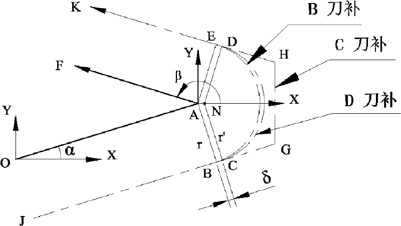
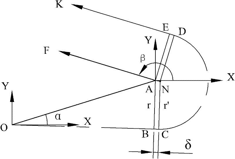
[0063] figure 1 It shows the algorithms and tool center trajectory of B tool compensation, C tool compensation and D tool compensation. Line segment JB, arc BE with radius r and line segment EK are tool center loci for B tool compensation; line segment JB, line segment BC, arc CD with radius r′, line segment DE and line segment EK are tool center loci for D tool compensation ; Line segment JB, line segment BG, line segment GH, line segment HE and line segment EK are the tool center trajectory of C tool compensation.

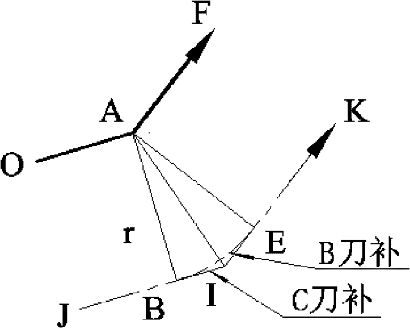
[0064] figure 2 It shows the analysis of the tool compensation algorithm when the sharp corner of the cam profile is an obtuse corner. The line segment JB, line segment BI, line segment IE and line segment EK are the tool center trajectory of the C tool compensation; the line segment JB, arc BE and line segment EK are the tool center trajectory of the B t...


PUM


Abstract

The invention discloses a radius compensation algorithm for a convex contour closed-angle linear and circular arc composite transitional cutting tool, namely D-type cutting tool radius compensation. The radius compensation algorithm comprises the following steps of: taking a ling segment BC, a circular arc CD and a line segment DE as a cutting tool central track of the radius compensation algorithm for the linear and circular arc composite transitional cutting tool; calculating the coordinate of a switching point; and establishing or canceling cutting tool radius compensation. Because the cutting tool central track is extended at a convex contour closed-angle transitional part, the cutting tool cannot always contact an A point any more, and the problem of closed-angle burn caused by B-type cutting tool radius compensation which stays at a closed-angle part for an overlong time is effectively solved. Due to the adoption of circular arc transition at the convex contour closed-angle transitional part, the cutting tool central track is smooth and continuous, and the problem that frequently acceleration and deceleration are required and the processing speed is difficult to improve because of broken line transition of C-type cutting tool radius compensation. The length of the cutting tool central track of the D-type cutting tool radius compensation is longer than that of the cuttingtool central track of the B-type cutting tool radius compensation, and is shorter than that of the cutting tool central track of the C-type cutting tool radius compensation.

Description

technical field [0001] The invention relates to a new type of numerical control processing technology, in particular to a compensation algorithm for the radius compensation of a cam profile sharp angle straight line arc compound transition tool. Background technique [0002] The sharp corner transition problem is a traditional problem in CNC machining. At present, most CNC system tool radius compensation adopts B-type tool radius compensation (abbreviated as B tool compensation) or C-type tool radius compensation (abbreviated as C tool compensation). [0003] B-type tool radius compensation calculates the movement track of the tool center according to the part contour size and tool radius in the program segment, uses the intersection point of the convex contours of adjacent program segments as the center of the circle, and uses the tool radius as the radius to connect the tool corresponding to the program segment profile Center locus, and connections must be tangent. After ...

Claims


Application Information

Patent Timeline
Patent Type & Authority Applications(China)
IPC IPC(8): G05B19/404
Inventor 王春林盛彭全海阎长罡
Owner DALIAN JIAOTONG UNIVERSITY
Why Eureka
Try Eureka